


19
MAXIMUM RUN TIMER
SMART™ Self adjusting MAximum Run Timer (Patent
Pending)
The RS4000 has a Self adjusting MAximum Run Timer, SMART™
(patent pending). The amount of time for the first few cycles of
operation are registered and averaged within the motor controller
circuitry. After the first few initial cycles, if the gate is activated and
no other command is given or an end limit (open or close) is not
reached in the previously counted cycle time plus approximately 4
seconds, the operator will be turned off.
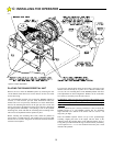
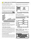
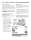
FINAL SETTING OF THE CLOSE TIMER
To alter the amount of time that the Close Timer will hold the gate
open, adjust the timer potentiometer located on the control board.
See Figure 19.
The Close Timer is adjustable from 2 to approximately 60 seconds.
Turning the potentiometer clockwise increases the delay; turning it
counterclockwise decreases the delay.
D: STARTING THE
You are now ready to install and connect the auxiliary
equipment. INSTALLATION STEPS DETAILED IN
SECTIONS A, B, C AND D MUST BE COMPLETE
BEFORE PROCEEDING.
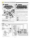
1. Vehicle Detectors: If a Vehicle Detector (Safety Loop)
is to be a part of this installation, start with this first.
Connect the Vehicle Detector to AC power and the Loop
in accordance with the Manufacturer's instructions and
the information contained in this manual. Do not
connect to the terminal strip of the RS4000 at this time.
Test the Vehicle Detector independently using the
presence lamp on the front panel of the detector and a
metal plate over the loop. When you are satisfied that
the Detector is working properly, connect the output
wires to the "REVERSING" terminal on the control
panel of the RS4000.
Give the gate an open command and allow the Timer to
Close to start the gate to close. Place the metal plate
over the Loop and observe that the gate reopens.
2. Shadow Loop: See Section B regarding Vehicle
Detector Loop Blanking for Swing Gates.
3. Free Exit: If a "FREE EXIT" Detector is installed, connect the
output wires of this Detector to the Terminal #5 (FREE EXIT).
It is acceptable to have more than one device connected to the
same Terminal. Place the metal plate over the FREE EXIT
LOOP and observe that the gate opens to the fully open
position. Leave the metal plate on the loop for at least one
minute. Observe that the gate does not close. Remove the plate
from the Loop and observe that the gate closes. (Some Vehicle
Detectors will "tune out" a constant obstruction to the loop after
15 to 30 minutes.)
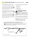
4. Installing other entry devices: After you are satisfied that all
the loops are functioning properly, proceed with the installation
of the additional devices, such as a Radio Receiver, Telephone
Entry or Key Pad. Connect the Radio Receiver to the Radio
Terminal. Observe the precautions regarding radio receivers
described on page 15. Other entry devices MUST be connected
to the appropriate terminal (See pages 15 & 16 for terminal
descriptions). The recommended minimum distance between the
gate or fence and an accessory input device is 10 feet.
E: INSTALLATION NOTES FOR AUXILIARY EQUIPMENT
BASIC OPERATIONAL GUIDE
•If the gate is fully closed an Open Button, Alternate, Radio or Free
Exit input will cause the gate to begin moving in the open direction.
•If the gate is fully open a Close Button, Alternate, or Radio input
will cause the gate to begin moving in the close direction.
•If the gate is moving in a Close direction a Close Non-Contact
Sensor or a Close Contact Sensor input will cause the gate to stop,
pause and reverse for approximately 2 inches in the Open direction.
•If the gate is moving in a Close direction an Open Button, Radio,
Reversing, or Free Exit Loop input will cause the gate to stop, pause
and reverse and run in the Open direction.
•If the gate is moving in a Close direction a Stop Button or Alternate
input will cause the gate to stop. A subsequent Alternate input will
cause the gate to begin moving in the Open direction.
•If the gate is moving in an Open direction an Open Non-Contact
Sensor, Open Contact Sensor input or an Open Overload activation
will cause the gate to stop, pause and reverse for approximately 2
inches in the Open direction.
•If the gate is moving in an Open direction a Stop or Alternate input
will cause the gate to stop. A subsequent Alternate input will cause
the gate to begin moving in the Close direction.
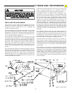
MANUAL OPERATION FEATURE: The gate can be moved
open or close in case of power failure or other need to move the gate
manually from any position except fully closed without disconnecting the
operator arm. Remove power from the unit (if not already off) and firmly
grasp the leading edge of the gate. Push or pull the gate in the direction
desired. The amount of force required to move the gate will depend on the
setting of the adjustable torque drive, the gate weight, and the inherent
friction of the overall system. Manual Operation is to be attempted only
when the operator is not moving under power.
F: END USER INSTRUCTIONS GATE OPENER OPERATION AND SAFETY
IMPORTANT SAFETY INSTRUCTIONS. TO REDUCE THE RISK OF SEVERE INJURY OR
DEATH: READ AND FOLLOW ALL INSTRUCTIONS IN THIS MANUAL!
WARNING!