


15
labeled as COMMON, then connect this to Terminal #1 or #0 of the
RS4000 control panel. Connect the other contact to one of the
following terminals depending on function desired: Terminal #2
(ALTERNATE), Terminal #4 (RADIO OPEN), Terminal #5 (FREE
EXIT), Terminal #6 (OPEN) or Terminal #7 (CLOSE). If no
identification of the connections is noted at the device, then the two
wires may be connected to terminals #1 and one of the terminals
above (again depending on desired function) in any order.
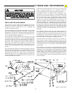
Keypads, Card Readers and Telephone Entry Systems are typically
located remotely from the RS4000. The wiring used is low voltage
CLASS 2. Be sure to run an independent conduit for this wiring from
the entry device to the RS4000. The wire size should be #16 or #18
stranded for ease of handling.
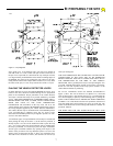
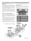
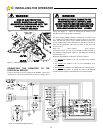
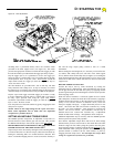
WIRING VEHICLE DETECTORS
There are three connections that need to be made; 1) the AC power to
the detector, 2) the control connection to the RS4000, and 3) the
connection to the loop. All these connections will be made at the
vehicle detector connector. Follow the wiring instructions provided
by the vehicle detector manufacturer.
VEHICLE DETECTOR POWER
Vehicle detectors may be ordered for 115 VAC or 24 VAC
operation. Allstar recommends that a 115 VAC Vehicle Detector be
used. The 115 VAC may be obtained from the electrical service to
the RS4000 operator .
CONNECTING THE VEHICLE DETECTOR TO
THE RS4000
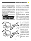
For a REVERSING LOOP connection of the vehicle detector, the
"relay" or "presence" output of the detector will be connected to
Terminal #11 (REV LOOP) of the RS4000 and the COMMON wire
will be connected to Terminal #0 or #16 (COMMON) of the
RS4000. As long as a relay closure is present on these two lines, the
RS4000 will not allow the gate to close. If the gate is opening, the
gate will continue to open. If the signal is removed before the Timer
to Close times out, the gate will close after the Timer to Close has
completed its cycle.
For a FREE EXIT connection of a Vehicle Detector, the RELAY or
PRESENCE output signal will be connected to Terminal #5 (FREE
EXIT) and the RELAY COMMON signal connected to Terminal #0
or #16(COMMON) of the RS4000. DO NOT CONNECT THE
FREE EXIT OUTPUT SIGNAL TO ANY OTHER TERMINAL,
SUCH AS RADIO RELAY, BECAUSE THE GATE WILL
CLOSE
AFTER REACHING THE OPEN LIMIT AND THE TIMER TO
CLOSE HAS COMPLETED ITS CYCLE, EVEN THOUGH THE
VEHICLE HAS NOT EXITED THE FREE EXIT LOOP.
WARNING!
RISK OF ENTRAPMENT!
TO REDUCE THE RISK OF INJURY OR DEATH:
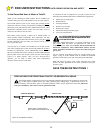
LOCATE KEYPAD, CARD READER, KEY SWITCH OR
SIMILAR ENTRY DEVICES IN A LOCATION WHERE A
USER CAN NOT REACH THROUGH THE GATE OR
FENCE TO ACTIVATE THE GATE OPERATOR. THE
RECOMMENDED DISTANCE BETWEEN THE GATE
OR FENCE AND ACCESSORY SWITCH IS 10 FEET.
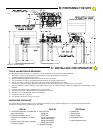
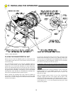
C: INSTALLING THE OPERATOR
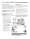
# NAME
DESCRIPTION
0 COMMON
Common connection for low voltage
signal inputs, terminals 2 thru 15.
1 24 VAC
Provides maximum 10 VA auxiliary
power for accessories.
2 ALTERNATE
Momentary input, must be released
and re-entered to be recognized.
This input is used for “COMMAND OPEN/COMMAND
CLOSE” applications. The 1st signal will cause the gate to
begin opening. A 2nd signal received during the open cycle
will stop the gate immediately. A 3rd signal will close the gate.
Connect appropriate access control devices to this terminal
and #0 or #16 COMMON.
3 24 VAC
Provides maximum 10 VA auxiliary
power for accessories.
4 RADIO OPEN
Momentary input, must be released
and re-entered to be recognized.
Once activated the gate will open fully. Activation while the
gate is closing will cause it to re-open.
5 FREE EXIT
Momentary or continuous input.
Once activated the gate will open fully. Activation while the
gate is closing will cause it to re-open. Continuous activation
while the gate is open will prevent the Timer-To-Close function
from automatically closing the gate.
6 OPEN
Momentary or continuous signal. On/
Off mode set by Switch #1
Once activated the gate will open fully. Activation while the
gate is closing will cause it to re-open. Continuous activation
while the gate is open will prevent the Timer-To-Close function
from automatically closing the gate. Continuous signal
required to move the gate when in the alarm mode.
7 CLOSE
Momentary or continuous signal. On/
Off mode set by Switch #1
Once activated the gate will close fully. Activation while the
gate is opening has no effect. Continuous signal required to
move the gate when in the alarm mode.
8 STOP
Momentary or continuous signal.
Overrides all other signals. Once activated, the gate will
immediately stop and await a new command. If the STOP
input is continuously activated, the gate will not move.
9 SHADOW
LOOP
Momentary or continuous signal.
This input is active only when the gate is at rest in the fully
OPEN position, it has no effect on the gate when fully closed
or when closing or opening. Continuous activation will prevent
the gate from moving in the close direction. When the input is
removed normal operation is resumed. This input is intended
for a vehicle loop detector to sense a vehicle in the gate path.
Connect here and to terminal #16 COMMON. Multiple devices
may be connected in parallel.
TERMINAL STRIP REFERENCE CHART