


Rev.: 20120307
Platform: DBALL
Firmware: CHRYSLER Remote Start Ready Installation
© 2012 Directed.All rights reserved.
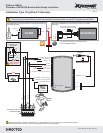
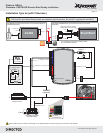
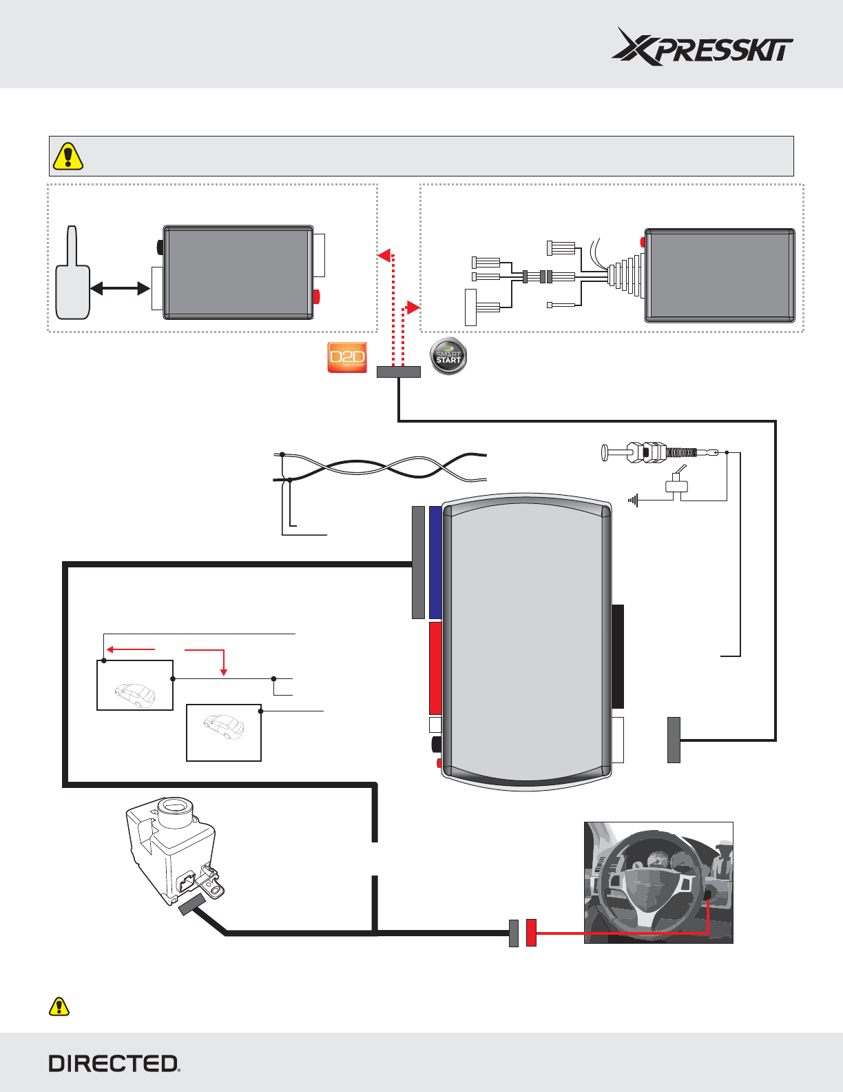
Installation Type 2a (with T-Harness)
Page 7
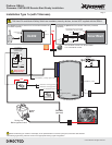
10
DBALL
Programming button
LED
4
14
12
2
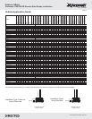
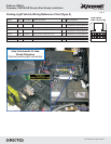
Twisted pair in the kick panel
White/Orange
White/Gray, White
or White/Pink
RF
Ignition
Barrel
Facing view
Behind Ignition Switch
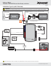
5: White/Orange: FTCAN High
6: White: FTCAN Low
2: Green/Black: (-) Parking Lights*
(-) Driver door pin
Purple wire in
driver kick panel
10: Yellow/Black: RAPOFF
8: Violet/Green: MUX*Parking Light
9: Violet/Brown: Parking Light MUX*
Hood Pin
Neutral Safety Switch
6: White/Black: (-) Hood
See page 9 for
wiring information
Important!
The Hood Pin and Neutral Safety Switch are mandatory security devices, but are NOT supplied with the DBALL.
TX
(-) Ground
RX
(+) 12v
CHTHD1
(optional)
Wires are listed by pin numbers. This display is not representative of connector pin layouts, which are often stacked.
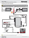
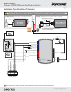
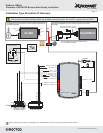
The XL202 and antenna are not included and MUST be
purchased separately.
optional
LED
OR
Programming
Button
4
4
XL202
Antenna
(+)12v
TX
(-) Ground
RX
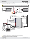
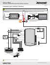
SmartStart is not included. It MUST be purchased
separately.
optional and
You can either connect to an XL202 module
or to a SmartStart module.
LED
SmartStart
Configuration Wires (Gray & White)
Connect Gray wire to (-) Ground
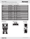
5 pins
D2D (4 pins, white)
4 pins
2 pins
(+)12v
TX
(-) Ground
RX
OR*
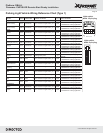
*See Parking Lights wiring reference chart for the appropriate Parking Lights configuration.
XOVER
CABLE