


Rev.: 20120307
Platform: DBALL
Firmware: CHRYSLER Remote Start Ready Installation
© 2012 Directed.All rights reserved.
16
10
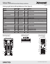
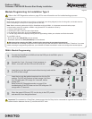
DBALL
RF
Programming button
LED
4
14
12
2
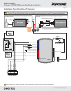
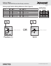
2: Violet/Yellow: J1850
8: Yellow
9: Orange/Yellow
Module-Sentry Key
Remote Entry
Violet/Brown, Pin 2
1
Connector
side view
(+) Start, Pin 4
(+) Ignition, Pin 3
J1850
Sentry Key
(+) Ignition
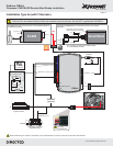
8: Violet/Green: Multiplex Output
9: Violet/Brown: Multiplex Output
14: Black: (-) Ground(-) Ground
13: Red: (+) 12v(+) 12v
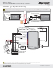
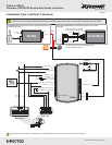
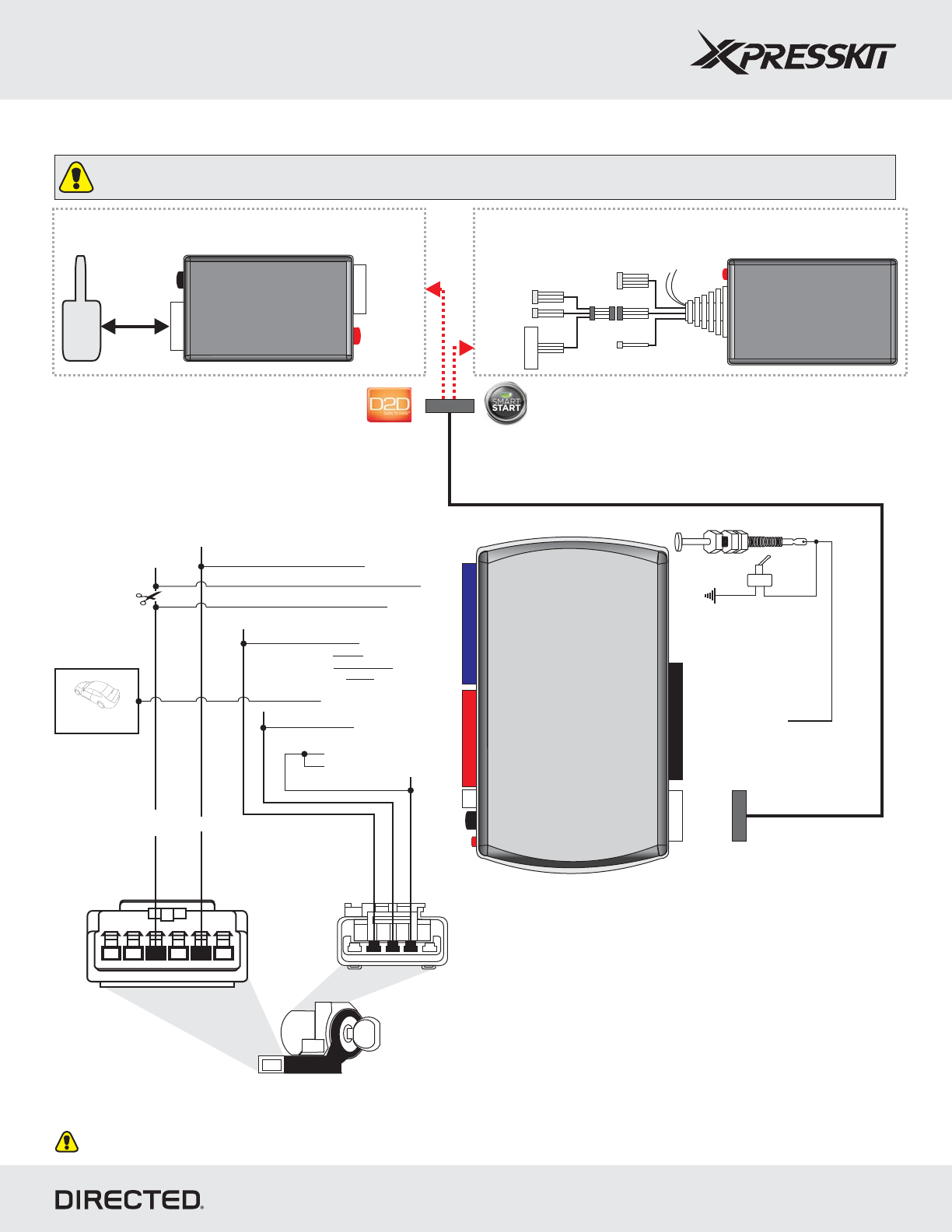
Installation Type 5 (without T-Harness)
Page 16
Important!
The Hood Pin and Neutral Safety Switch are mandatory security devices, but are NOT supplied with the DBALL.
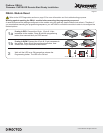
TX
(-) Ground
RX
(+) 12v
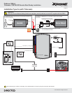
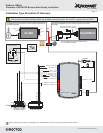
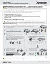
The XL202 and antenna are not included and MUST be
purchased separately.
optional
LED
OR
Programming
Button
4
4
XL202
Antenna
(+)12v
TX
(-) Ground
RX
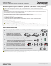
SmartStart is not included. It MUST be purchased
separately.
optional and
You can either connect to an XL202 module
or to a SmartStart module.
LED
SmartStart
Configuration Wires (Gray & White)
Connect Gray wire to (-) Ground
5 pins
D2D (4 pins, white)
4 pins
2 pins
(+)12v
TX
(-) Ground
RX
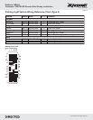
Wires are listed by pin numbers. This display is not representative of connector pin layouts, which are often stacked.
Hood Pin
Neutral Safety Switch
6: White/Black: (-) Hood
7: Gray/Black: (+) Ignition
11: Yellow/Red: (+) Start
Parking Lights
See page 17 for
wiring information
2: Green/Black: (-) Parking Lights
12: Brown/Red: (+) 12v
(+) 12v
XOVER
CABLE