


INSTALLATION
TMS7 SERIES ME00070B 9
Installation
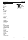
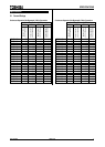
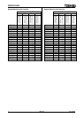
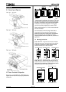
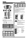
6.1 General Layout Diagrams
TMS7-4007 ~ TMS7-4055
TMS7-4075 ~ TMS7-4132
TMS7-4150 ~ TMS7-4800
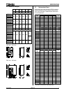
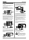
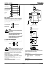
4.2 Power Termination Configuration
The bus bars on models TMS7-4150 ~ TMS7-4800 can be
adjusted to provide four different input/output power terminal
configurations.
I
n
p
u
t
/
O
u
t
p
u
t
I
n
p
u
t
O
u
t
p
u
t
Input/Output Output Input
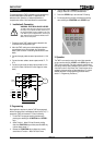
To adjust the bus bar configuration first remove the TMS7 cover
and main control module. Next loosen and remove the bus bar
fixing bolts. The bus bars can then be removed and reinstalled
into the starter in the desired configuration. The fixing bolts
should then be refitted and tightened to a torque of 8.5NM.
When re-orienting bus bars L1, L2, L3 the current transformers
must also be relocated.
Care must be taken to ensure that foreign matter does not
contaminate the jointing compound and become trapped
between the bus bar and its mounting plate. If the paste does
become contaminated, clean and replace with a jointing
compound suitable for aluminium to aluminium, or aluminium to
copper joints.
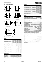
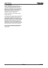
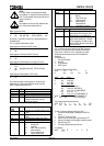
4.3 Mounting Instructions
Models TMS7-4007 ~ 4132 can be wall mounted or installed
inside another enclosure. These models can be mounted side
by side with no clearance but a 100mm allowance must be
made top and bottom for air intake and exhaust.
100mm Minimum Clearance100mm Minimum Clearance100mm Minimum Clearance
1
0
0
m
m
M
i
n
i
m
u
m
C
l
e
a
r
a
n
c
e
1
0
0
m
m
M
i
n
i
m
u
m
C
l
e
a
r
a
n
c
e
1
0
0
m
m
M
i
n
i
m
u
m
C
l
e
a
r
a
n
c
e
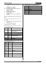
Models TMS7-4150 ~ 4800 have an IP00 rating and must be
mounted in another enclosure. These models can be mounted
side by side with no clearance but a 200mm allowance must be
made top and bottom for air intake and exhaust.
200mm Minimum Clearance
200mm Minimum Clearance
2
0
0
m
m
M
i
n
i
m
u
m
C
l
e
a
r
a
n
c
e
2
0
0
m
m
M
i
n
i
m
u
m
C
l
e
a
r
a
n
c
e