


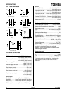


CONTROL CIRCUITS
16 ME00070B TMS7 SERIES
or 02h 42h 31h 30h 35h 42h
03h
1. 35h (ASCII hex) = 5H = 00000101
42h (ASCII hex) = Bh = 00001011
Note: 03h is the EXT character (end of transmission) and is
not part of the message.
2. 00000101 = 01010000
3. 01010000 + 00001011 = 01011011
4. 02h + 42h + 31h + 30h = A5h
5. A5h + 5Bh = 100h
6. The least significant byte is zero so the message and
LRC match.
Response or status bytes are sent from the TMS7 as an ASCII
string.
STX [d1]h [d2]h [d3]h [d4]h LRC1 LRC2 ETX
d1 = 30h
d2 = 30h
d3 = 30h plus upper nibble of status byte right shifted by four
binary places.
d4 = 30h plus lower nibble of status byte.
For example status byte = 1Fh, response is
STX 30h 30h 31h 3Fh LRC1 LRC2 ETX
Status bits (positive logic 1 = true)
Status
Bit
Function Comment
Status.7 50 Hz Only one of either Status.7 or
Status.6 can be at logic 1 when the
TMS7 is operating.
Status.6 60 Hz
Status.5 - Unallocated
Status.4 Soft stop
Status.3 Positive
phase
rotation
Will be at logic 0 when there is a
negative phase rotation.
Status.2 - Unallocated
Status.1 - Unallocated
Status.0 - Unallocated
Status_1 bits (negative logic 0 = true)
Status Bit Function Comment
NOT
Status_1.7
-
NOT
Status_1.6
-
NOT
Status_1.5
-
NOT
Status_1.4
Restart
Delay
NOT
Status_1.3
Overload Motor is operating in an overload
condition.
NOT
Status_1.2
Run
NOT
Status_1.1
Output On
NOT
Status_1.0
Power On
Trip bits (negative logic 0 = true). The table below shows the
complement of these bits to give positive logic (1 = true).
Status Bit Function
NOT Trip.7 Phase Loss
NOT Trip.6 Undercurrent
NOT Trip.5 Phase Rotation
NOT Trip.4 Overcurrent
NOT Trip.3 Over Temperature
NOT Trip.2 Installation
NOT Trip.1 Stall Protection
NOT Trip.0 Thermistor