


TROUBLE SHOOTING
30 ME00070B TMS7 SERIES
Code
Description
TMS7 and reconnect the motor in 6 Wire.
Incorrect main control module.
The TMS7 is fitted with an incompatible main control
module.
1. Fit a suitable main control module.
u
CPU error
Reset the TMS7. If the problem persists contact your
supplier.
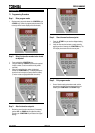
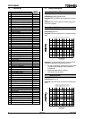
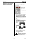
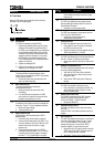
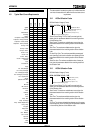
9.2 Fault History
The TMS7 includes a Fault History Log that records the last
eight trip events. Each trip is numbered. Trip number 1 is the
most recent trip with trip number 4 being the oldest.
1 - 4
Trip Number
1 = Most recent trip
2 = Previous trip
4 = Oldest trip
Trip Code
.
.
.
The Fault History can be viewed by selecting Function 101.
Fault History and using the <UP> and <DOWN> keys to scroll
through the Fault History.
CAUTION
NOTE:
The TMS7 records trips in the Fault History log
immediately after they are detected, this requires
control voltage to be present after the trip. Trips
caused by or involving a loss of control voltage
may not be recorded.
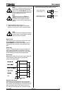
A ‘marker’ can be inserted into the Fault History log to identify
trips that have occurred after placement of the ‘marker’. To
insert a ‘marker’ enter the programming mode and move to
Function 101. Fault History. Then simultaneously depress the
<UP> and <DOWN> and <STORE> keys. The marker is added
as the most recent fault and is displayed as three horizontal
lines as shown below.
CAUTION
NOTE:
Trip makers must be separated by at least one trip
and cannot be placed consecutively.
9.3 General Faults
Symptom Cause
Uncontrolled start.
Power factor correction capacitors
connected to the TMS7 output. Remove
any power factor correction from the output
of the soft starter. Connection of power
factor correction capacitors to the output of
a soft starter can result in damage to the
SCRs so they should be checked by using
the SCR test described in section 9.4 Tests
and Measurements.
Damaged SCRS. Verify soft starter
operation using the SCR test described in
section 9.4 Tests and Measurements.
Damaged firing circuit. Verify the TMS7
SCR firing circuit using the Power Circuit
Test described in section 9.4 Tests and
Measurements.
TMS7 will not
operate.
Local push buttons not active.
The TMS7
may be in remote control mode. (Refer to
Function 20. Local/Remote Operation)
Remote control inputs not active. The
TMS7 may be in local control mode. (Refer
to Function 20. Local/Remote Operation)
Faulty start signal. Verify any circuits
connected to the TMS7 remote control
inputs. The state of the remote circuits is
indicated by the TMS7 remote control input
LEDs. The LEDs are illuminated when there
is a closed circuit. For there to be a
successful start there must be a closed
circuit across the start, stop and reset
circuits.
No, or incorrect control voltage. Ensure
the correct control voltage is applied to the
inputs A1, A2, A3.
Restart delay active. The TMS7 cannot be
started during the restart delay period. The
period of the restart delay is set using
Function 31. Restart Delay.
Auto-reset function active. If there has
been a trip and the auto-reset function is
active the fault must be manually reset
before a manual restart can be attempted.
(Refer to Functions 70, 71, 72 & 73 )
TMS7 in programming mode. The TMS7
will not run while in programming mode.
The motor will not
accelerate to full
speed.
Start current too low. Check the load is
not jammed. Increase start current using
Function 2. Current Limit.
Function setting
cannot be made or
are not recorded.
Incorrect programming procedure.
Function settings must be stored using the
<STORE> button. Refer to section 7.1
Programming Procedure for further detail.
Function settings are locked. Ensure that
Function 112. Function Lock is set for
Read/Write.