


TROUBLE SHOOTING
TMS7 SERIES ME00070B 29
Section 9 Trouble Shooting
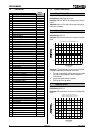
9.1 Trip Codes
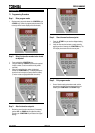
When the TMS7 enters the trip state the cause of the trip is
indicated on the LED display panel.
Code
Description
0
Shorted SCR
The TMS7 has detected a shorted SCR(s).
1. Determine the affected phase using the 3 phase
indicators LEDs located on the left hand side of
the TMS7 cover. Damaged SCRs are indicated by
an extinguished phase indicator LED (all phase
indicator LEDs should be illuminated when input
voltage is present but the motor is not running).
SCR damage can be verified using the Power
Circuit Test described in the Test & Measurement
chapter of this section.
2. Replace the damaged SCR.
3. Reset the trip condition by removing and
reapplying control voltage to the TMS7.
2
Overcurrent trip
The motor has been overloaded and the motor’s
thermal limit, as calculated by the TMS7 motor thermal
model, has been reached.
1. Remove the cause of the overload and let the
motor cool before restarting.
3
Motor thermistor trip
The motor thermistors have indicated an
overtemperature situation.
1. Identify and correct the cause of the motor
overheating.
2. If no thermistors are connected to the TMS7,
ensure there is a closed circuit across the motor
thermistor input (terminals C1 & C2).
4
Current imbalance trip
An imbalance in the phase currents has exceeded the
limits set in Function 7. Current Imbalance Sensitivity.
1. Monitor the supply voltage
2. Check the motor circuit
5
Supply frequency trip
Supply frequency has varied outside the TMS7’s
specified range.
1. Correct the cause of the frequency variations.
2. Check the three phase supply to the TMS7. Loss
of all three phases is seen by the TMS7 as a 0Hz
situation and may be the cause of a supply
frequency trip.
3. Check the three phase supply to the TMS7 is
connected to input terminals L1, L2, L3. Incorrect
connection of the incoming supply to the output
te
rminals T1, T2, T3 means there is no supply
connected to the TMS7 input. This will be seen as
Code
Description
connected to the TMS7 input. This will be seen as
a 0Hz situation and may the cause of a supply
frequency trip.
6
Phase rotation trip
The TMS7 has detected a phase rotation that has
been prohibited by the setting made in Function 30.
Phase Rotation Protection.
1. Change the incoming phase rotation.
7
Stall trip
The TMS7 has measured a current equal to the limit
set in Function 9. Stall Protection.
1. Identify and correct the cause of the
instantaneous overload event.
8
Power circuit fault
The TMS7 has detected a fault in the power circuit.
1. Ensure that the motor is correctly connected to
the TMS7 and verify the circuit.
2. Check that voltage is correctly applied to all three
TMS7 input terminals (L1, L2 & L3).
9
Undercurrent trip
The TMS7 has measured a run current lower than the
limit set in Function 8. Undercurrent Protection.
1. Identify and correct the cause of the undercurrent
event.
F
Heatsink overtemperature trip
The TMS7 heatsink temperature sensor has indicated
and excess heatsink temperature.
1. Verify that the TMS7 has sufficient ventilation.
2. Verify that cooling air is able to freely circulate
through the TMS7.
3. Verify that the TMS7 cooling fans (if fitted) are
working.
P
Invalid motor connection
The TMS7 cannot detect a valid motor circuit.
1. Ensure the motor is connected to the TMS7 in a
valid configuration. Refer to Section 5 Power
Circuits for further detail.
C
RS485 communication fault
The RS485 link connected to the TMS7 has been
inactive for a period of time greater than set in
Function 60. RS485 – Timeout Protection.
1. Restore the RS485 link.
E
EEPROM read/write failure
The TMS7 has failed to read or write to the internal
EEPROM.
Reset the TMS7. If the problem persists contact your
supplier.
Out of range FLC
The TMS7 has detected that the motor is connected in
the 3 Wire configuration and that Function 1. Motor
FLC or Function 80 Motor FLC (secondary motor
settings) has been set in excess of the TMS7’s
maximum capability for this connection format.
1. Reduce the motor FLC setting and then reset the
TMS7. Note that the TMS7 cannot be reset until
the FLC setting has been corrected.
2.
Alternatively, remove control voltage from the
TMS7 and reconnect the motor in 6 Wire.