


CONTROL CIRCUITS
TMS7 SERIES ME00070B 13
Control Circuits
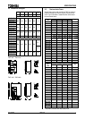
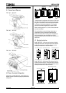
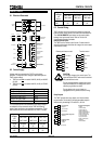
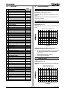
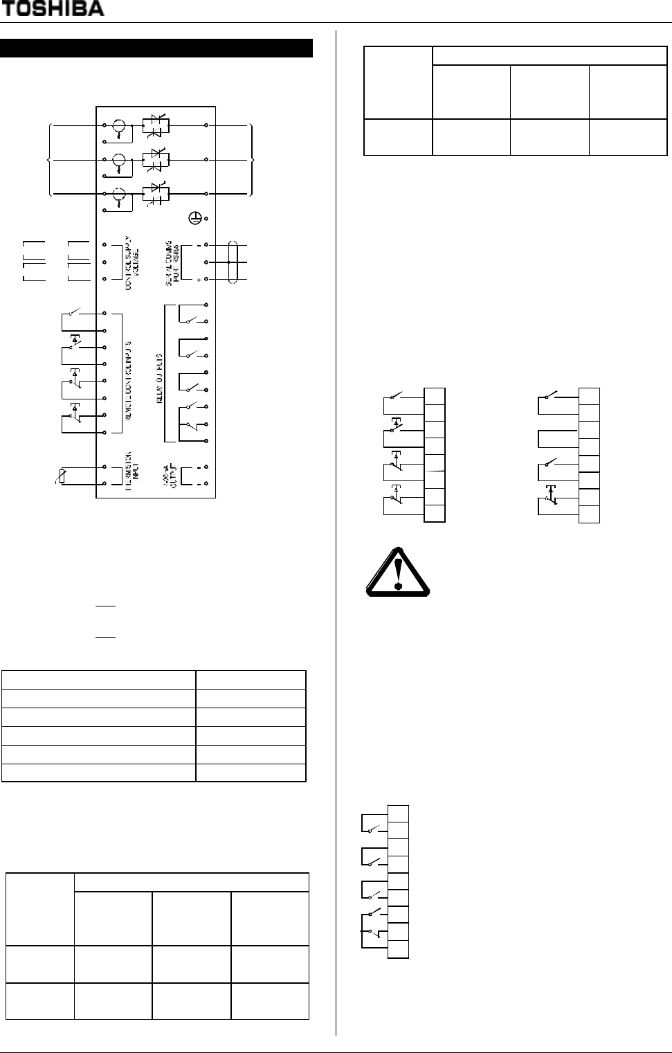
6.1 Electrical Schematic
FLC SELECT
I43
I44
I11
I12
I21
I22
I33
RESET
STO P
I34
START
OROR
C7
C6
4-20mA OUTPUT
(MOTOR CURRENT)
PRO GRAMMABLE
O UTPUT C
(Tripped)
RUN O UTPUT
R34
R33
L2B
L3B
L1B
E
T2
RS485 SERIAL
INTERFACE
GND
C5
C4
C3
R43
R44
MO TO R
THERMISTO R
R24
R23
L1
L2
L3
T1
T3
A1
A2
A3
R14
R12
R11
C1
C2
3 PHASE
SUPPLY
TO MO TO R
PRO GRAMMABLE
O UTPUT B
(St art /Run)
PRO GRAMMABLE
O UTPUT A
(Main Cont act or)
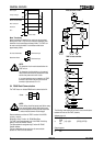
C24 models
230V
+10
-15
-15
+10
400V
C45 models
575V
+10
-15
-15
+10
460V
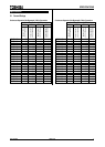
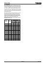
6.2 Control Supply
Voltage must be connected to the TMS7 control voltage
terminals. The required control voltage is dependent upon the
TMS7 model ordered.
• TMS7xxxx-xx-C24-xx models: 230VAC (A2-A3) or 400VAC
(A1-A2)
• TMS7xxxx-xx-C45-xx models: 460VAC (A1-A2) or 575VAC
(A2-A3)
TMS7 Model Maximum VA
TMS7-4007~TMS7-4022 11VA
TMS7-4030~TMS7-4055 18VA
TMS7-4075~TMS7-4110 24VA
TMS7-4132~TMS7-4500 41VA
TMS7-4600~TMS7-4800 56VA
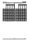
For circumstances where the available control supply voltage is
not suitable for direct connection to the TMS7 the following
range of auto-transformers are available as accessories. These
auto-transformers can be mounted within the TMS7 in models.
Part Number Input
Voltages
(C24
Models)
TMS7-4007~
TMS7-40047
TMS7-4030~
TMS7-4110
TMS7-4132~
TMS7-4800
110/460
VAC
995-00821-
00
995-00823-
00
995-00824-
00
110/575
VAC
995-00825-
00
995-00827-
00
995-00828-
00
Part Number Input
Voltages
(C45
Models)
TMS7-4007~
TMS7-4022
TMS7-4030~
TMS7-4110
TMS7-4132~
TMS7-4800
110/230
VAC
995-00829-
00
995-00831-
00
995-00832-
00
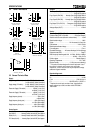
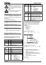
6.3 Control Wiring
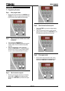
TMS7 operation can be controlled using either the local push
buttons, remote control inputs or the serial communications link.
The <LOCAL/REMOTE> push button can be used to switch
between local and remote control. Refer to Function 20.
Local/Remote Operation for details.
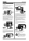
Remote Control Inputs
The TMS7 has four remote control inputs. Contacts used for
controlling these inputs should be low voltage, low current rated
(Gold flash or similar).
Remote push button control
Reset
Stop
Start
I21
I22
I33
I34
I11
I12
I43
I44
FLC Select
Two wire control
Reset
Stop
Start
I21
I22
I33
I34
I11
I12
I43
I44
FLC Select
CAUTION
CAUTION:
Do not apply voltage to the control inputs. The
inputs are active 24VDC and must be controlled
with potential free circuits.
Ensure contacts/switches operating the control
inputs are suitable for low voltage, low current
switching ie, gold flash or similar.
Ensure cables to the control inputs are
segregated from AC power and control wiring.
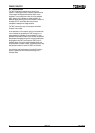
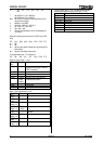
Relay Outputs
The TMS7 provides four relay outputs, one fixed and three
programmable. Functionality of the programmable outputs is
determined by the settings of Functions 21, 22 & 23.
R23
R24
R33
R34
R43
R44
R12
R14
R11
*
=
d
e
f
a
u
l
t
f
u
n
c
t
i
o
n
a
l
i
t
y
Functionality Assignme
n
- Tripped
- Overcurrent trip
- Undercurrent trip
- Motor thermistor trip
- Starter overtemperature
t
- Phase imbalance trip
- Electronic shearpin trip
- Low current alarm
- High current alarm
- Motor overload alarm
- Start/Run
- Main Contactor
Programmable
Output C
(*Tripped)
Run Output
Programmable Output B
(*Start/Run)
Programmable
Output A
(*Main Contactor)