


TROUBLE SHOOTING
TMS7 SERIES ME00070B 31
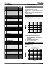
Symptom Cause
Erratic motor
operation and
tripping.
SCRs not latching. SCRs require a
minimum current flow to ‘latch’ on. In
situations where very small motors are
being controlled by large soft starters the
current drawn may be insufficient to latch on
the SCRs. Increase motor size or reduce
soft start size.
Soft stop ends
before the
programmed ramp
time.
Motor will not stall. The TMS7 has
significantly reduced the voltage applied to
the motor without detecting a reduction in
motor speed. This indicates that with
present motor loading further control of the
voltage will be ineffectual, hence the soft
stop function has halted.
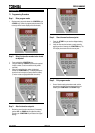
TMS7 display
shows a ‘h’
The START button on the local control
panel is stuck. Release the button to
restore normal operation.
TMS7 will not enter
the programming
mode.
The TMS7 is running. The TMS7 must be
stopped before programming mode can be
accessed.
No, or incorrect control voltage. Ensure
the correct control voltage is applied to the
inputs A1, A2, A3.
9.4 Tests & Measurements
Test Procedure
Run performance
test.
This test verifies correct operation of the
TMS7 during run.
1.
Measure the voltage drop across each
phase of the TMS7 (L1–T1, L2–T2,
L3–T3). The voltage drop will be less
than approximately 2 VAC when the
TMS7 is operating correctly.
Control input test
This test verifies circuits connected to the
TMS7 remote control inputs. (Start, Stop,
Reset & FLC Select)
1. Measure the voltage across each
input. With the remote circuit closed
there should be 0VDC measured. If
24VDC is measured the switch/control
is incorrectly connected or faulty.
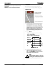
Start performance
test.
This test verifies correct operation of the
TMS7 during start.
1. Determine the expected start current
by multiplying the settings made in
Function 1. Motor Full Load Current
and Function 2. Current Limit.
2. Start the motor and measure the
actual start current.
3. If the expected start current and the
actual start current are the same, the
TMS7 is performing correctly.
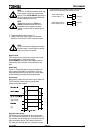
Power circuit test.
This test verifies the TMS7 power circuit
including the SCR, firing loom and control
module.
1. Remove the incoming supply from the
TMS7 (L1, L2, L3 and control supply).
Test Procedure
2. Remove the motor cables from the
output terminals of the TMS7 (T1, T2
& T3).
3. Use a 500 VDC insulation tester to
measure the resistance between the
input and output of each phase of the
TMS7 (L1-T1, L2-T2, L3-
T3). Note that
low voltage ohm meters or multi-
meters are not adequate for this
measurement.
4. The measured resistance should be
close to 33kΩ and approximately
equal on all three phases.
5. If a resistance of less than about
10kΩ is measured across the SCR,
the SCR should be replaced.
6. If a resistance greater than about
60kΩ is measured across the SCR
there could be a fault with the TMS7
control module or firing loom.