


POWER CIRCUITS
TMS7 SERIES ME00070B 11
Power Circuits
5.1 Overview
TMS7 starters can be wired with a number of different power
circuits depending on application requirements.
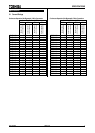
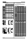
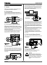
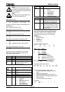
5.2 3 Wire Connection
This is the standard connection format. Supply voltage is
connected to the starter input terminals L1, L2 & L3. The motor
cables are connected to the soft starter output terminals T1, T2
& T3.
M
(OPTIONAL )( OPTI ONAL)
K1 M F1
K1 Line Contactor
F1 Sem iconduct or Fuses
Legend
L2B
L3B
L1B
E
T2
L1
L2
L3
T 1
T3
3 PHASE
SUPPLY
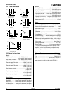
5.3 3 Wire Connection (Bypassed Operation)
TMS7 starters can be bypassed while the motor is running.
Special terminals (L1B, L2B, L3B) are provided for connection of
the bypass contactor. Use of these terminals enables the TMS7
to continue to provide all protection and current monitoring
functions even when bypassed.
The TMS7 Run Output (Terminals R34 & R33) should be used
to control operation of the bypass contactor. The bypass
contactor can be AC1 rated for the motor full load current.
M
K1M Line Contactor
K2M Bypass Contactor
F1 Semiconduct or Fuses
Legend
L2B
L3B
L1B
E
T2
L1
L2
L3
T1
T3
3 P HA SE
SUPP LY
(O PT IONAL)(OPTIONAL)
K1M F1
K2M
R33
R34
K 2M
Run Output
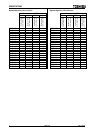
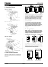
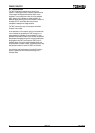
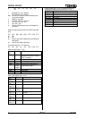
5.4 6 Wire Connection
TMS7 units are capable of 6 Wire (Inside Delta) connection as
well as 3 Wire connection. When connected in this configuration
the soft starter carries only phase current, this means the motor
FLC current can be 50% greater than the soft starter’s FLC
current rating.
(OP TIONAL)
K1M F1
K1 Line Contactor
F1 Se micon ductor Fuses
Lege nd
M
L2B
L3B
L1 B
E
T2
L 1
L2
L3
T1
T3
3 PHASE
SUPPLY
U1
V1
W1
U2
V2
W2
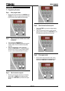
Connect the three OUTPUT terminals (T1, T2, T3) of the TMS7
to the motor windings ensuring that the connections are made to
one end of each winding only. It is imperative to connect the
output of the TMS7 to the same end of each winding and this is
usually marked on the motor terminations.
L1
L2
L3
T1
T2
T3
MOTOR TERMINALS
6 WIRE CONNECTION
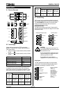
The six terminations to the motor windings are usually arranged
in two rows of three so that the links can be fitted across from
the top three terminations to the lower terminations. In this case
connect the TMS7 to the top terminations only. Connect the
other three motor terminals to the input of the TMS7 in a manner
that connects the end of each winding to a different phase from
the input.
This is most easily achieved by replacing each delta link in the
motor terminal box by one phase of the controller. For example
if the delta links are fitted U1-V2,V1-W2,W1-U2
- Connect the incoming phases to L1,L2,L3 on the TMS7.
- Connect the TMS7 to the motor. T1-U1, T2-V1, T3-W1
- Connect the other motor terminals to the TMS7’S input W2-L1,
U2-L2, V2-L3
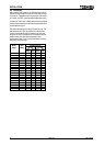
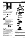
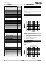
5.5 6 Wire Connection (Bypassed Operation)
TMS7 units are capable of 6 Wire (Inside Delta) connection and
can be bypassed.
(OPTIONAL)
K1M F1
M
K1M Line Con tactor
K2M Bypass Co ntacto r
F1 Semiconductor Fuses
Legend
L2B
L3B
L1B
E
T2
L1
L2
L3
T 1
T3
3 PHASE
SUPPLY
U1
V1
W1
U2
V2
W2
K2M
R33
R34
K2 M
Run Output
5.6 Power Factor Correction
If static power factor correction is employed, it must be
connected to the supply side of the soft starter.
CAUTION
CAUTION:
Under no circumstance should power factor
correction capacitors be connected between the
soft starter and the motor. Connecting power
factor correction capacitors to the output of the
soft starter will result in damage to the soft
starter.