


21
Installation
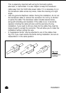
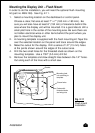
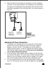
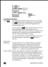
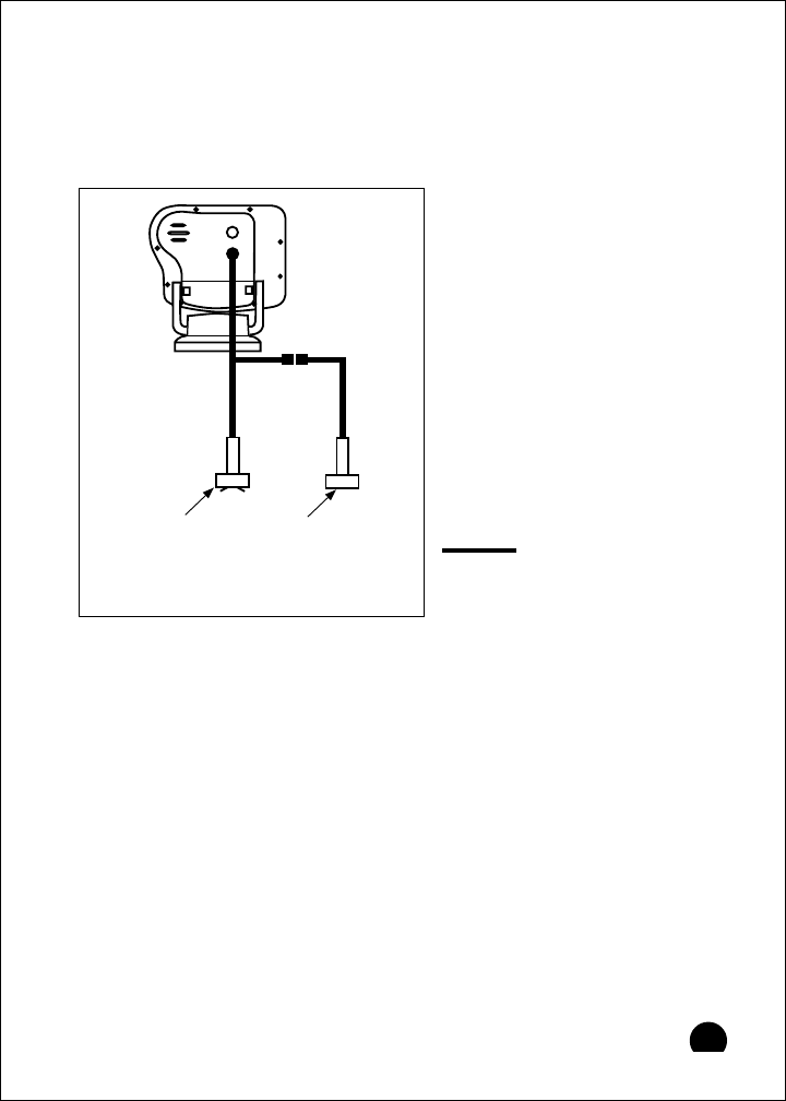
2. Plug the cable from the depth-only transducer into the receptacle
connector on the optional speed- and temperature-only transducer.
The speed- and temperature-only transducer then connects at the
transducer receptacle of the FishFinder 465. This is shown below in
Fig. 2-15.
Making the DC Power Connections
1. The display unit is designed for use on boats with 12V DC power
systems. (The unit can operate as long as the actual voltage is
between 10.8 and 16V DC.) The display unit can be wired to a
negative-ground system, or both the negative and positive supply
lines may be “floating” above ground.
This unit is not intended for
use on boats with positive ground.
2. The 6-foot power cable supplied with the display unit should reach
the source of DC power. On a small boat, connect the power leads
directly to the main battery isolation switch or breaker. On a larger
boat, route the power leads to the DC power distribution panel.
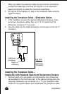
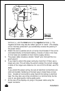
3. It is very important that you connect the power leads correctly. See
Fig. 2-16. At the power source, connect the
red
wire to the
positive
Fig. 2-15
Cable for Speed
and Temperature
Sensor
Sensor for
depth only
Sensor for
speed and
temperature