


SECTION SIX: Interfacing the 957 system
957 INSTALLATION MANUAL, Revision C1 Page 51
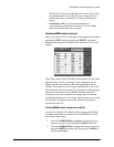
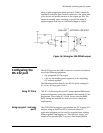
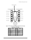
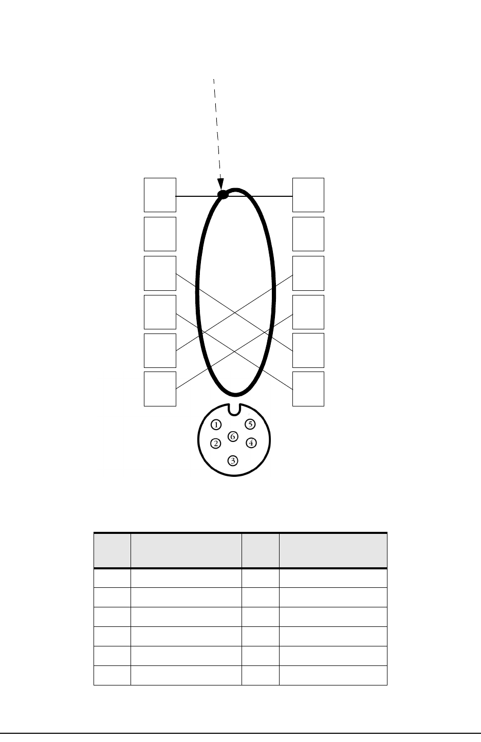
Figure 17: 957 aux ports’ interface diagram (wiring side view, solder cup)
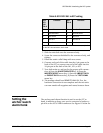
Table 8: 957 to 957 wiring
957
Pin #
Function 957
Pin #
Function
1 Ground shield 1 Ground shield
2 No connect 2 No connect
3 Aux In B 5 Aux Out B
4 Aux Out A 6 Aux In A
5 Aux Out B 3 Aux In B
6 Aux In A 4 Aux Out A
957 6-PIN AUX CONNECTOR
957 6-PIN AUX CONNECTOR
1
2
3
4
5
6
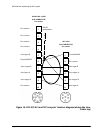
1
2
3
4
5
6
No connect
Aux input A
Ground/shield
Aux output A
Aux input B
Aux output B
Shield termination
Aux output A
Aux input A
Aux output B
Aux input B
Ground/shield
Pin number
No connect
Pin number