


SECTION SIX: Interfacing the 957 system
Page 40 957 INSTALLATION MANUAL, Revision C1
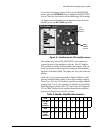
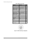
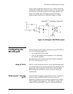
Figure 15: NMEA connector pin configuration
Table 5: NMEA connector pins
Description Wire color Pin
NMEA port 1 input A brown 3
NMEA port 1 input B blue 1
NMEA port 1 input ground white with blue stripe 4
NMEA port 1 output A violet 12
NMEA port 1 output B gray 7
NMEA port 1 output ground blue with white stripe 8
NMEA port 2 input A white with brown stripe 6
NMEA port 2 input B brown with white stripe 2
NMEA port 2 input ground white 5
NMEA port 2 output A yellow 15
NMEA port 2 output B orange 11
NMEA port 2 output ground black 10
RS-232 ground tan 17
RS-232 RX green 16
RS-232 TX red 18
External ground/foil drain white with orange shield 9
Reserved orange with white stripe 13
Honk out/200 PPNM (pulses
per nautical mile)
pink 14