


SECTION THREE: Installing and wiring the 2201
Page 22 957 Installation Manual, Revision C1
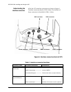
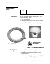
2. Coil any extra 2201-CA cable away from the 2201. Don’t
pinch the cable or make any sharp bends, and don’t run
the cable where it interferes with any controls.
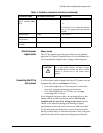
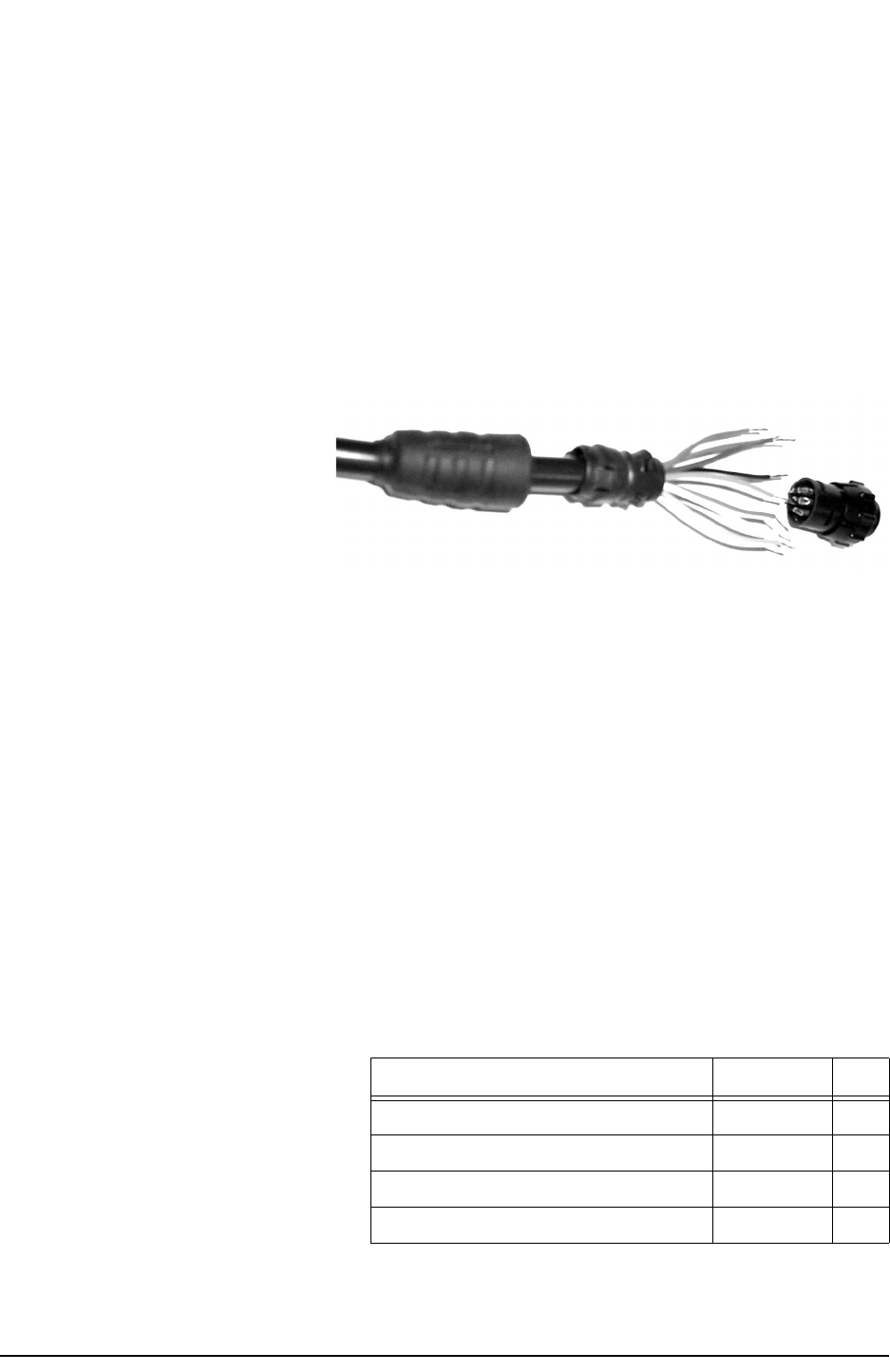
Re-fabricating the 957 connector (optional)
If you want to shorten the cable or remove its connector to
make more room to snake the cable, you can remove the
connector from the 957 end and then replace it:
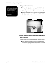
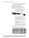
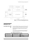
1. After shortening or snaking the cable, slide
the available heat shrink tubing onto the
cable, then slide the connector backshell
onto the cable, as shown below.
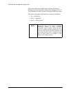
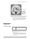
2. Prepare each wire for insertion into its solder
cup by stripping it and tinning it.
3. Carefully solder each wire to the appropriate
cup, as described in Table 2 below.
4. Slide the backshell down the cable and screw
it onto the connector body. It should be hand
tight.
5. Using the supplied screws, screw the strain
relief onto the backshell.
6. Slide the heat shrink tubing onto the connec-
tor. Be sure to leave room for the locking col-
lar to retract.
7. Heat the shrink tubing until it shrinks around
the connector, providing a watertight seal.
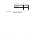
For the pin numbers and functions for the 957 end of the cable,
see Table 2 below.
Table 2: Wiring connections for 2201 cable
Description Wire color Pin
RS232 RX1 (Main receive port) Blue 1
RS232 RX2 (Aux receive port) Orange 2
RS232 TX1 (Main transmit port) Green 3
Signal gnd Brown 4