


SECTION FOUR: Installing and wiring the 2701
Page 28 957 Installation Manual, Revision C1
Installing the
AN205-P antenna
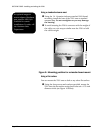
Choosing the antenna’s
mounting location
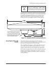
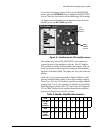
The 2701 operates with Northstar’s AN205-P “combo” GPS/
DGPS antenna. Mount the antenna high enough to clear any
objects and get an unobstructed view of the horizon in all
directions. Mount it low enough on the vessel to avoid extra
motion from pitching and rolling, and lower than any
high-power transmitting antennas, such as radar or satcom (see
Figure 8 on page 19 for recommended separation distances
between antennas). Keep the antenna at least six feet away
from objects that can “shade” GPS or differential signals.
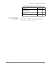
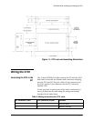
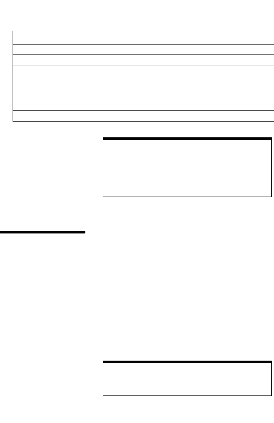
36GPS TX1 (Green)
4 20 BDM TX1 (Brown)
5 12 Power CTL (Black or Gray)
6 13 GND (White)
7 25 Power + (Red)
6 NC Drain Wire
NC KS131 Foil Shield
Table 3: Wiring connections for 2701 cable (cont.)
957 connector (7-pin) 2701 connector (25-pin) Function
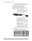
NOTE:
Double-check all wiring if you re-fabricate the
cable. A small, but significant, number of 2701’s are
damaged due to incorrectly wired connections.
Such damage is not covered under warranty. Be
sure you aren’t applying primary voltage directly to
any of the 2701’s signal input/output wires. This
may vaporize the internal circuit board conductors.
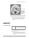
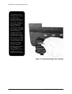
NOTE:
Before permanently installing the AN205-P, try
temporarily installing it and using the 957 to see if
the antenna location works well.