


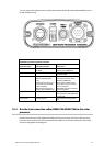
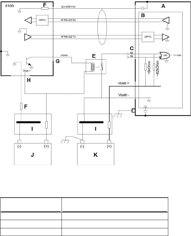
The radar processor has two remote power inputs with opposite active states which are OR’ed
together.
Pin 10 input (active low) is used by the 6000i or 6100i systems and Pin 12 input (active high) is used by
the 8000i system.
Pin 12 is tied to ground through the NS003107 cable, to allow control through Pin 10.
The radar processor has an active low input with a pullup resistor to Vbatt, to complement the open
collector output configuration of the 6000i or 6100i systems.
There is a choice of two different modes for powering the radar ON/OFF:
If you want the radar to power ON automatically when the radar processor is powered ON,
connect the White/Orange wire to a NMEA ground in the junction box.
If you want the radar to power ON automatically whenever the 6000i or 6100i is ON,
program the Honk Output as REMOTE PWR in the 6000i or 6100i. This option is contained in
the Alarms menu. (To access the Alarms menu, repeatedly press the * key until the Alarms
menu is visible.) You must also connect the Pink wire to the White/Orange wire in the
junction box.
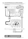
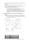
12.7.3 Configure the remote power control for a 6000i or 6100i (different power
sources)
When the 6000i or 6100i and the radar processor have isolated power supplies, or are located more
than 16.5 ft (5 meters) apart, there is a choice of two different modes for powering the radar ON/OFF:
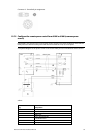
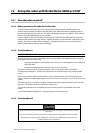
If you want the radar to power ON automatically whenever the 6000i or 6100i is ON, use the
following power ON/OFF configuration:
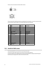
where:
Key Component
A Radar processor
B Main PCB
C NMEA/Comms port
Northstar 25 kW Radar Installation Manual
34