


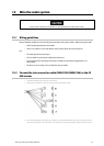

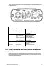
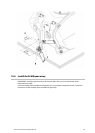
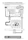
7. Connect the five interconnection cable connectors (B, C, D, E, and F) to the J connectors as follows:
Cable connector J connector
B (P2) J2
C (P1) J1
D (P3) J3
E (P4) J4
F (P5) J5
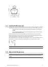
8. Close the scanner with the screws.
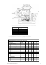
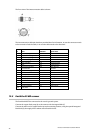
The wiring details for the connector ends B, C, D, E, and F are as follows:
NS003105/NS003106 Interconnection cable - connector ends
Pin Color AWG Size B C D E F
1 Blue / Gray (big) #16
1
2 Purple / Brown (big) #16
1
3 White / Orange (big) #16
2
4 Red / Green (big) #16
2
5 Black / Sky (big) #16
1
6 Black #22
6
7 Drain wire (coax line) #24 2
8 No connection
9 Yellow / Pink (big) #16
2
10 Axis line #24 1
11 Yellow (thin) #24 3
12 Green (thin) #24
5
13 White (thin) #24 4
14 Drain wire #24
2
Northstar 25 kW Radar Installation Manual
25