


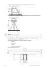

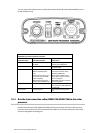
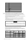
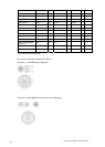
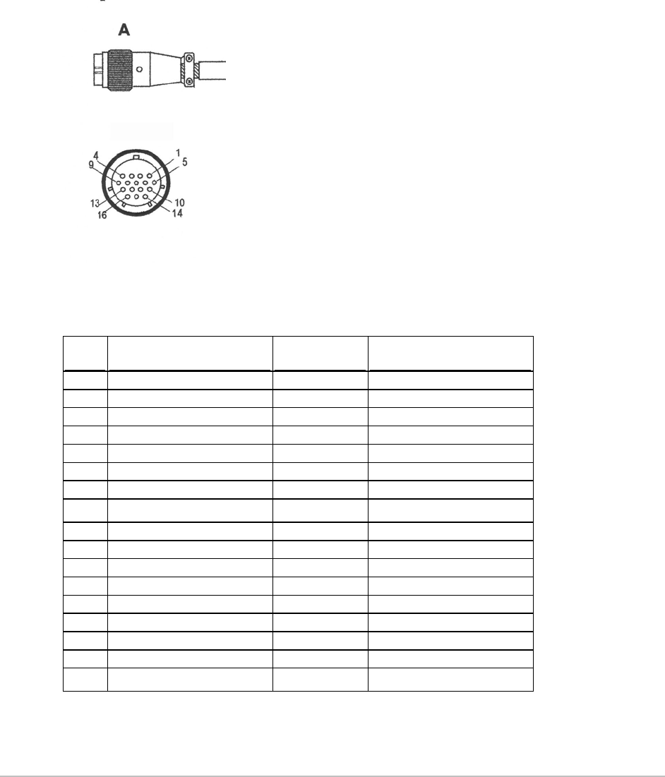
The front view of the interconnection cable is shown:
The interconnection cable pin details are provided here for information, in case the connector needs
to be removed to feed the cable, or in case the cable needs to be shortened.
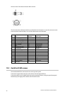
Pin Color AWG Size Signal name
1 Blue / Gray (big) #16 Motor Ground
2 Purple / Brown (big) #16 Motor Ground
3 White / Orange (big) #16 Motor Power
4 Red / Green (big) #16 Motor Power
5 Black / Sky (big) #16 Scanner Ground
6 Black #22 Analog Ground
7 Drain wire (coax line) #24 Video Ground
8 No connection
Not used
9 Yellow / Pink (big) #16 Scanner Power
10 Axis line #24 Video
11 Yellow (thin) #24 RS-485 Comm+
12 Green (thin) #24 Bearing Zero
13 White (thin) #24 RS-485 Comm-
14 Drain wire #24 Trigger Ground
15 Shield line #24 Trigger
16 Orange (medium) #22 Bearing Pulse
Shell Braid shield
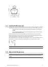
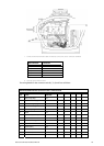
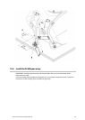
12.5 Earth the 25 kW scanner
The Earth bolt MUST be connected to the vessel's ground system.
Connect the copper Earth strap (A) to the scanner with a hexagonal bolt (C).
Connect the other end of copper Earth strap to the mounting location, using the special hexagonal
Earth bolt (B), then apply silicon sealant around both the bolts.
Northstar 25 kW Radar Installation Manual
28