


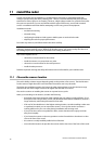
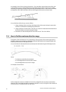
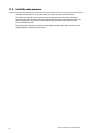

An example of an A-B Line is shown in the picture. If you install the scanner below the A-B line, the
scanner will be too low. It will be difficult to acquire distant targets and the superstructure will be
more likely to impede the passage of the beam and generate false echoes. If the scanner is installed
too high above the A-B line, the beam will miss close targets and increase sea clutter return.
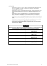
You can find the A-B line for any vessel as follows:
1. Using a drawing of the vessel, lay a rule along the line of the main deck and continue this
forwards as a dashed line extending beyond the bow.
2. Using a protractor, measure the
θ° value (for your scanner model) below the dashed line at
the bow and draw in a new line along this angle.
3. Extend the new line back beyond the stern of the vessel. This is the A-B line.
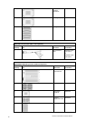
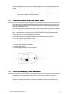
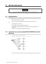
11.3 How to find the maximum detection range
Propagation of the radar beam can vary, depending on the properties of the air through which it's
traveling. Under normal conditions, the distance that the radar beam travels is approximately 10%
further than the distance to the optical horizon.
You can calculate the theoretical distance traveled by the radar beam using the following formula:
D = 2.23 (
√h1 + √h2)
where:
D is distance traveled by the radar beam
h1 is the height above sea level of the scanner
h2 is the height above sea level of a target
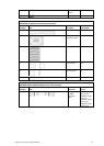
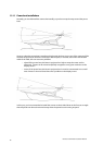
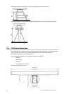
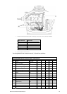
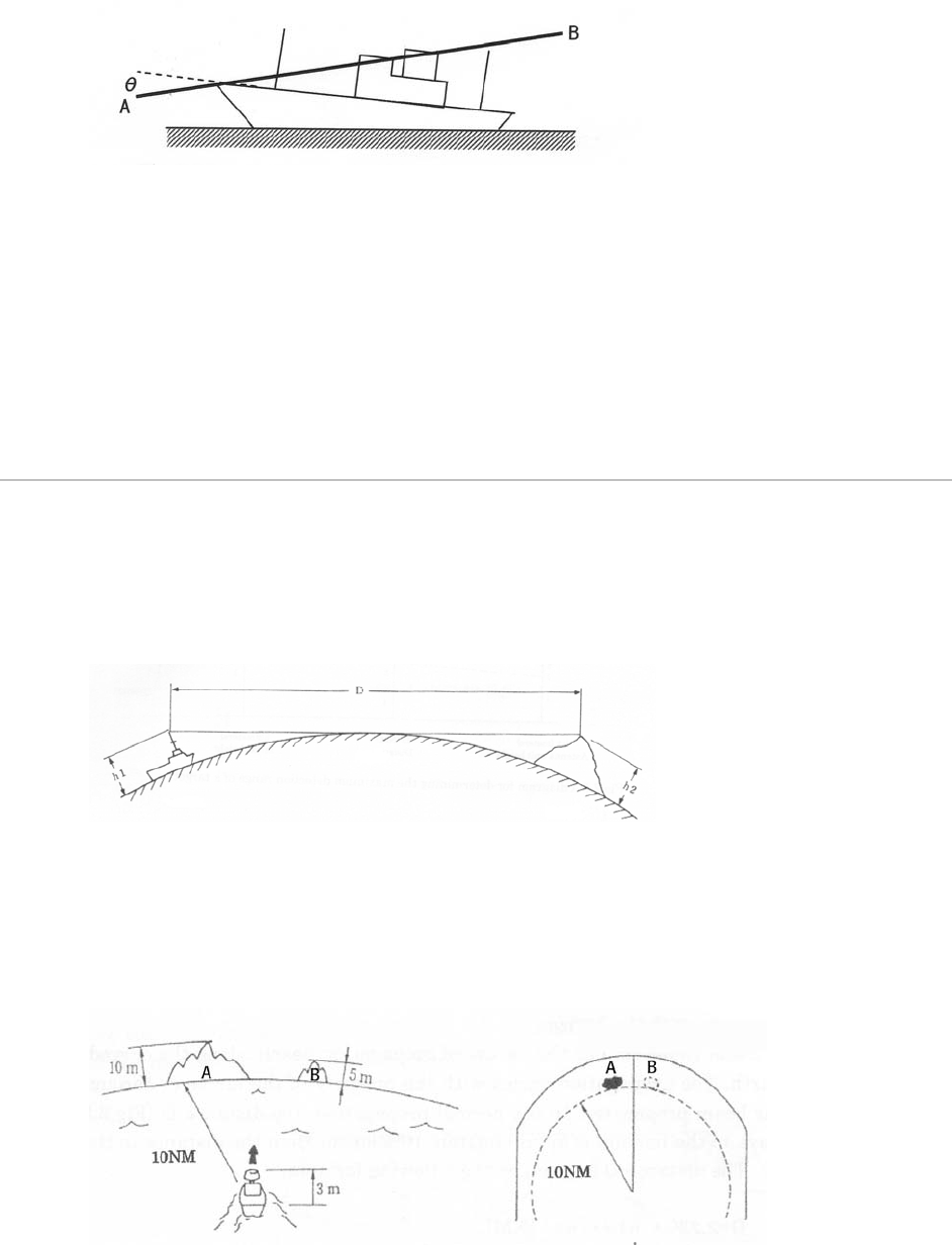
An example is shown below:
In this example, the scanner is installed on the vessel at a height of 10 ft (3 m) above sea level (h1).
Island A is 33 ft (10 m) high (h2) and for comparison, Island B is 16.4 ft (5 m) high (h2). Both islands are
at a distance (D) of 10 nautical miles from the vessel.
Northstar 25 kW Radar Installation Manual
18