


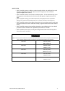
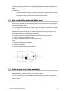


Calculations using the formula show that, at this distance, the radar can only detect objects that are
more than 25 ft (7.6 m) high, which means that Island A is shown on the radar but Island B is not
shown.
Remember that:
the maximum detection range of the radar is limited by the curvature of the Earth's surface
under normal conditions of wave propagation.
bad weather conditions can reduce the maximum detection range
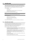
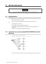
11.4 How to reduce false echoes and shadow zones
False echoes can be produced on the radar display if the scanner is installed too close to an object on
the vessel's superstructure. This object can block the radar beam and reflect it back, generating the
false echoes and shadow zones.
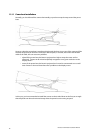
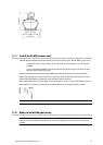
If you're having problems with false echoes and/or shadow zones, check if it's possible to re-install the
scanner at a higher location where the radar beam will be clear of any obstructions.
If not, try relocating the scanner away from the central keel line of the vessel to the starboard side.
This will move any shadows to the port side, maximize the radar view of your give way sector, and
ensure a clear view of the area around the vessel at the bow.
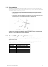
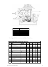
Use the following formula to calculate the distance that you'll need to move the scanner:
Ls = 0.4R + D/2 (when R is less than 49 ft [15 m])
Ls = 0.025R + D/2 (When R is greater than or equal to 49 ft [15 m])
where:
Ls = distance to be moved from the keel line
D = diameter of the obstacle
R = distance between the antenna and the obstacle
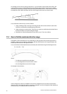
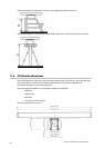
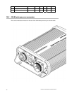
11.5 Install an open array scanner on a trestle
Depending on your chosen location for the scanner, it may be easier to install the scanner if you
fabricate a trestle or radar mast on which you can mount the scanner.
In this case, the base of the trestle must be installed parallel to the water surface. Orient the trestle so
that the main cabling from the scanner will face the stern. Make sure that the edges of the trestle
won't trap water.
Northstar 25 kW Radar Installation Manual
19