


Tracker500/500i User Manual38
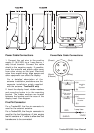
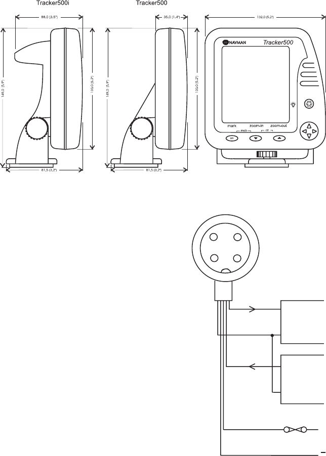
Power Cable Connections
1. Connect the red wire to the positive
supply (11-16.6 VDC) via a 1 amp fuse or 1
amp circuit breaker. Connect the cable
shield to the negative supply. If possible,
route the antenna and power cable away
from other wiring on the boat. Electrical
noise from engine wiring, bilge pumps and
other equipment can affect the display.
For a detailed description of the
antenna installation procedure see the
separate installation guide supplied
with the antenna. Tracker500
only
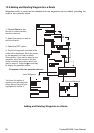
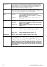
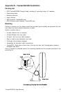
2. Insert the display head, rubber washers
and mounting knobs in to the mounting
bracket. The rubber washers are located
between the bracket and the case of the
display head. See diagram.
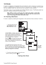
Five Pin Connector
For a Tracker500, the five pin connector is
used for the external antenna.
For a Tracker500i, the five pin connector is
used for the fuel transducer. A twin engine
fuel kit contains a ‘Y’ cable to allow two fuel
transducers to be connected.
(Green)
(Shield
& Brown)
1
2
3
4
(Red)
(White)
+(a)
-(b)
+(a)
-(b)
Differential
Receiver
NMEA Output
RTCM 104 input
9600 baud
Autopilot
or
Repeater
(White)
(Green)
(Brown)
RED
SHIELD
+
12VDC
1 amp fuse
Power/Data Cable Connections