


LA000605D © 2007 Navman New Zealand. All rights reserved. Proprietary information and specications subject to change without notice.
1
1.0 Introduction
The Navman Jupiter 32 module is a complete GPS receiver designed for surface mount
assembly integration. The Jupiter 32 provides a simple, cost effective GPS solution for
application designers. Application integration will vary primarily with respect to antenna system
design and EMI protective circuitry.
The Jupiter 32 is the successor to the established Jupiter 30, being electrically compatible and
having a very small form factor. The provides an easy migration path for existing users requiring
very small packaging, low cost, high volume, greater sensitivity, lower power consumption and a
faster x.
Basic operation requires a power supply, GPS antenna system interface, relevant EMI
protection, and the design and layout of a custom PCB. This document outlines the following
design considerations and provides recommended solutions:
Hardware application information
This section introduces the system interface and provides the following physical specications:
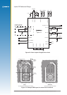
a. electrical connections (SMT pad interface)
b. mounting (PCB pad layout dimensions)
c. manufacturing recommendations
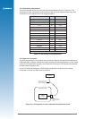
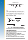
d. application circuit interface
It also discusses fundamental considerations when designing for RF, and presents the antenna
system design overview. This covers the following topics:
a. PCB layout
b. antenna system design choices
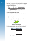
A sample solution is presented and discussed. Due to the nature and complexity of GPS signals,
it is recommended that application integrators adhere to the design considerations and criteria
described in this document.
Software application information
This section provides answers to some common questions that might not have been covered in
the above topics.
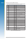
2.0 Hardware application information
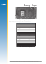
The Jupiter 32 module provide 34 Land Grid Array (LGA) pads for electrical connections. The
sections that follow introduce the physical and relative functional specications for application
integration.
Note: The electrical connections can carry very low level GPS signals at 1.57542 GHz. The
layout must be designed appropriately with consideration of the frequencies involved.