


LA000605D © 2007 Navman New Zealand. All rights reserved. Proprietary information and specications subject to change without notice.
9
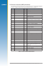
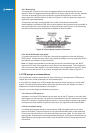
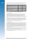
The features of each type of antenna are shown in Table 2-4, comparing an externally
mounted active antenna with a passive patch antenna mounted on the same PCB as the
module.
Feature Passive antenna Active antenna
antenna requires close proximity to receiver yes no
consumes power no yes
can be mounted remote from receiver no yes
gives good performance in poor signal situations no yes
has built in additional ltering no yes
low cost yes no
requires a coaxial connector no yes
Table 2-4: Passive and active Patch antenna features
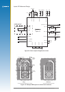
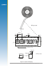
2.4.2 Active antenna
An active antenna comprises a passive antenna with a built in LNA that requires a power
supply. Active antennas are used when the antenna input is connected to the receiver
through a coaxial cable (usually longer than 3 m) or any high loss transmission path.
The GPS signals experience loss in the transmission path from the antenna. The loss is
overcome by the antenna’s LNA, which amplies the signal before it enters the transmission
path.
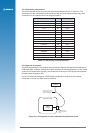
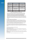
The amplication is also used to enhance the signal in areas of low signal. If the coaxial
cable is shorter than 3 m it may experience too much gain at the receiver and degrade the
performance. There are some variations as to how the antenna will receive its power, but it is
usually supplied through the coaxial cable via the antenna input as shown in Figure 2-5.
Refer to Table 2-5 for the recommended active antenna characteristics.
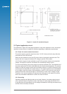
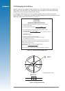
2.4.3 Passive antenna
A passive antenna does not require any power because it has no amplier. This is not the
best choice if signal strength is a concern, however, it may be sufcient if the signal path is
kept to a minimum (usually below 300 mm). An advantage to using a passive antenna is the
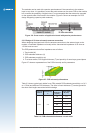
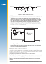
ability to mount directly onto the application. For best performance, a passive patch antenna
should have a metal ground plane (about 80 mm in diameter) placed directly under the
antenna, and it is advisable to shield the module and application circuits from the antenna.
For this reason the antenna and Jupiter 32 module should not be mounted on the same side
of the PCB (see Figure 2-6).
Any cover close to the antenna (called the superstrate) will cause the resonant frequency and
efciency of the antenna to drop. It is therefore recommended to keep any distance to the
superstrate to a minimum of 3 mm from the top surface of the patch.
See Table 2-5 for recommended characteristics of both passive patch and active antennas
for use with the Jupiter receiver.