


LA000605D © 2007 Navman New Zealand. All rights reserved. Proprietary information and specications subject to change without notice.
8
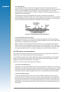
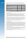
Notes:
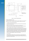
1. If a multi-layer PCB is used, the thickness is the distance from signal track to nearest
ground plane.
2. If the antenna connection is routed under the module, the track width should be
approximately halved for that section only.
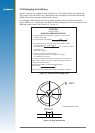
It is recommended that the antenna connection PCB track should be routed around the
outside of the module outline, kept on a single layer and have no bends greater than
45 degrees. It is not recommended (for production reasons) to route track under the module,
but if track has to route under the module, it should have a modied track width and solder
mask to avoid short circuits to the underside of the module.
To minimise signal loss and reduce the requirement for vias, it is recommended the signal
track not be placed on an inner layer of a multi-layer PCB.
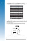
The PCB track connection to the RF antenna input must:
• have a characteristic impedance of 50 ohm
• be as short as possible
• be interfaced to a coaxial connector if an external antenna is used
• have max clearance to ground on the same layer, or at least be half the substrate thickness
• be routed away from noise sources such as: switching power supplies, digital signals,
oscillators and transmitters
The PCB track connection to the RF antenna input must not have:
• vias
• sharp bends
• components overlaying the track
2.4 Antenna system design choices
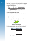
2.4.1 Antenna types
The role of the antenna is to lter, amplify and down-convert the incoming GPS signals into
an electric signal that can be processed by the receiver electronics within the RF section.
There are several designs of GPS antennas:
Monopole, or dipole, congurations.
Quadrilar helices.
Spiral helices.
Microstrips - active and passive.
Planar rings (“choke ring”), and other multipath-resistant designs.
There are special considerations for GPS antennas. They must be able to pick up and
discriminate very weak signals. GPS signals are circularly polarised, so the GPS antenna
must also be circularly polarised. The antenna gain pattern design is intended to enhance the
ability of the RF section to lter multipath and low elevation signals. An essential requirement
of any consumer GPS product is that the antenna is a stable electrical centre which is
coincident with the geometric centre and insensitive to the rotation and inclination of the
antenna.
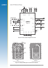
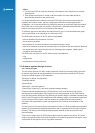
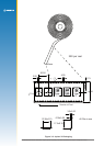
The main parts of the construction of the antenna consists of: (a) the omnidirectional antenna
element, (b) the antenna preamplier electronics, and (c) a ground plane (though not always
present). The industry has widely adopted the patch antenna as the most common and
practical design.
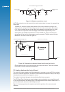
There are two major types of GPS antenna patch antennas: passive and active. The active
antenna has a built in LNA (Low Noise Amplier) to increase the strength of the signal, and to
compensate for the signal loss in a long cable connection.