


LA000605D © 2007 Navman New Zealand. All rights reserved. Proprietary information and specications subject to change without notice.
17
on the part. The proper nozzle should also heat the component leads by either hot gas or hot
bar. The ideal reow prole should be the same as the one used for mounting the part and
depends upon the paste used. The reow zone can be shortened as long as the reow is
complete. The part should then be lifted off automatically during the transition from reow to
cool down cycles using a vacuum.
4.1.9 Site Redress and Cleaning
Once the part is removed, the site needs to be cleaned for attachment of a new package.
This may be done by vacuum de-soldering or wick. Low-temperature, blade style conductive
tools in conjunction with de-soldering braids can also be used. Once all residual solder is
removed, the site should be cleaned with appropriate solvent such as alcohol and a lint-free
swab.
4.1.10 Application of Solder Paste
For a precise and uniform solder paste deposition on the redressed site, it is recommended
that a miniaturized stencil for the individual component be used. The stencil should be
aligned under 50x to 100x magnication, depending on the part. After precise alignment, the
stencil should be lowered onto the PCB and the paste should be applied in one pass.
4.1.11 Placement and Attachment of the New Component
The new part should be placed on the site using a split-beam alignment where a dual
image of the part leads and the land pattern on the PCB can be viewed on a high-resolution
monitor. Once aligned, the part should be placed on the site and attached to the board using
the reow prole used for the part removal.
5.0 Software application information
5.1 Normal mode operation
In normal mode of operation, the baseband processor software runs continuously, providing
a navigation solution at the maximum rate of once per second. No power saving functions are
applied.
If the power to the module is disrupted, the restart time can be shortened to a warm or hot start
by keeping the RTC and SRAM contents valid with a backup battery on the VBATT input.
If the module has been turned off for longer than 2 hours, the unit will revert to a warm or cold
start. This is caused by the stored ephemeris data becoming invalid after 4 hours.
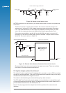
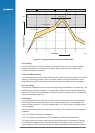
5.2 Power management
The TricklePower mode of operation can be enabled to reduce the average power consumption.
The main power is supplied to the module continuously. An internal timer wakes the processor
from sleep mode. The module computes a navigation position x, after which the processor
reverts to sleep mode. The duty cycle is controlled by a user-congurable parameter.
If ephemeris data becomes outdated, the TricklePower mode will attempt to refresh the data set
within every 30 minute period, or for every new satellite that comes into view.
With TricklePower set to a 20% duty cycle, a power saving of 50% can easily be achieved with
minimal degradation in navigation performance.
5.2.1 Adaptive TricklePower mode
In Adaptive TricklePower mode, the processor automatically returns to full power when signal
levels are below the level at which they can be tracked in TricklePower mode. This is the
default behaviour when TricklePower is active. Adaptive TricklePower is always enabled on
the Jupiter 32.