


70 mA Antenna supply current limit
R1
10R
C9
100nF
GND
SUPPLY_INPUT
3-5 VDC
200 mW
Q2
BC857B
Q1
BC857B
GND
GND GND
C8
100nF
C7
18pF
R10
1K
L3
120R @ 100 MHz
ANTENNA_SUPPLY
(V_ANT)
LA000605D © 2007 Navman New Zealand. All rights reserved. Proprietary information and specications subject to change without notice.
11
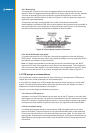
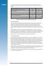
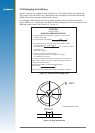
Figure 2-8: Simple current limiter circuit
NOTE: Ensure that the In-rush current of your active antenna does not cause it to approach the
current limit.
Transistor Q1 serves as a series pass transistor. Q2 is used to sense the current in the
antenna circuit, turning off Q1 if the voltage across the current sense resistor R1 exceeds
0.6 V. This circuit does not turn off the supply to the antenna, but merely limits it to a safe
value. With the components shown the supply will be limited to approximately 70 mA.
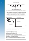
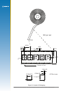
Other options are available to provide this function. MAXIM can supply a current trip IC
that will turn off the load if a preset supply current is exceeded. The part number for this is
MAX4785. The circuit is shown in Figure 2-9.
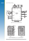
Figure 2-9: External Active Antenna Control and Current Limit circuit
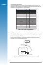
Electro-resistive fuses can be used to protect the supply over-current. These are available
from Bourns, Vitromon and other manufacturers.
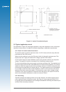
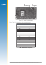
2.5 Jupiter adapter printed circuit board
The Jupiter 32 module supplied in the Development Kit is mounted on a carrier PCB in a method
typical of a customer application. This carrier PCB illustrates and implements many of the design
considerations discussed in this integrator’s manual.
The module is interfaced through a downward-facing 20-pin data connector.
The RTC (Real-Time Clock) backup supply voltage can be provided by an on-board lithium cell,
or from the Development unit backup supply. The adapter board carries a switch debounce IC to
provide reliable reset action from the Development unit.
Figure 2-10 (next page) shows the adapter board with the positions of the connectors and
indicators.
Antenna current limit using an IC
Jupiter GPS Module
A4
C5
GND
C5
100 nF
GND
GND
GND
GND
C4
100 nF
C6
18 pF
L2
120R @100 MHz
OUT
ON
IN
FLAG
3
1
2
4
5
PWR_IN
antenna power enable
U3
MAX4785EXK–T
antenna short circuit sense signal
F1
Jupiter 32