


LA000605D © 2007 Navman New Zealand. All rights reserved. Proprietary information and specications subject to change without notice.
10
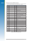
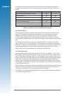
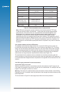
Characteristic Active antenna Passive antenna
polarisation
right-hand circular polarised right-hand circular polarised
receive frequency L1
1.57542 GHz
+/- 1.023 MHz
1.57542 GHz
> +/- 1.023 MHz
power supply 3 V (typ), 5 V max. –
DC current < 10mA at 3 VDC –
antenna gain –
+2 to 5 dBi with 1 dB loss (max)
in connections
total gain (includes
antenna gain, LNA
gain and cable loss)
≤ 26 dBi (Jupiter 20)
≤18 dBi (Jupiter 32)
–
axial ratio < 3 dB < 3 dB
output VSWR < 2.5 –
Table 2-5: Recommended antenna characteristics
Note: GPS active and passive antenna selection must include practical TTFF tests
in weak and strong outdoor environments – noting peak and average signal strength
measurements. This must be done in comparison with the antenna supplied in the
Development kit. Performance results and signal strength measurements must be
comparable to the reference antenna supplied. Passive antenna signal strength
measurements will be on average lower than an active antenna. This depends on size of
patch antenna/ground plane, distance from RF input, gain of the element and noise in the
application circuit. However, the TTFF should be comparable in open sky conditions. An
active antenna is recommended if peak performance is required in very weak or obscured
conditions.
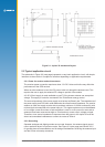
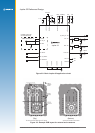
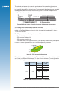
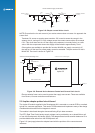
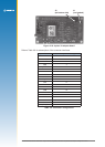
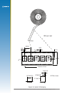
2.4.4 Jupiter module used as a GPS sensor
The adapter board reference design shows how a Jupiter 32 GPS receiver module can
be used with an external active antenna via a coax connector (See Figure 2-5). The same
design can be used with a passive patch antenna on the same PCB. The module is placed
so the connection between the antenna and the antenna input pad is as short as possible.
Also note, the PCB should have a complete ground plane on the patch side of the board
which serves as the ground plane required by the antenna (See Figure 2-6).
The serial data from the module must be connected to a local host processor, and care
should be taken so noise from these devices cannot enter the signal path or GPS antenna. It
is recommended that all digital devices are placed on the opposite side of the board from the
antenna.
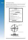
2.4.5 DC supply protection for an active antenna
Antenna DC supply current limit
When the Jupiter 32 receiver is used with an external active antenna, the DC supply in the
coax cable is vulnerable to over-current if a fault occurs in the antenna. For example, this can
happen if its cable gets crushed in a car door.
Warning: The Jupiter 32 module antenna power feed does not have internal current limiting.
Damage can occur if unlimited current is permitted to ow through the module antenna power
feed components.
The circuit shown in Figure 2-8 (next page) will provide over-current protection.