


49
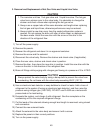
3. Removal and Replacement of Hot Gas Valve and Liquid Line Valve
CAUTION
1. The icemaker unit has 1 hot gas valve and 1 liquid line valve. The hot gas
valve has a strainer prior to the valve body. It is advisable to change the
strainer and check valves when replacing the hot gas valve.
. Always use a copper tube of the same diameter and length when replacing
the hot gas and liquid lines; otherwise performance may be reduced.
3. Always install a new drier every time the sealed refrigeration system is
opened. Do not replace the drier until after all other repair or replacement
has been made. Install the new drier with the arrow on the drier in the
direction of the refrigerant ow.
1) Turn off the power supply.
) Remove the panels.
3) Recover the refrigerant and store it in an approved container.
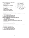
4) Remove the screw and the solenoid.
5) Disconnect the valve body. Remove the strainer and check valve (if applicable).
6) Place the new valve, strainer and check valve in position.
7) Remove the drier, then place the new drier in position. Install the new drier with the
arrow on the drier in the direction of the refrigerant ow.
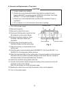
8) Braze all ttings while purging with nitrogen gas owing at a pressure of 3 to 4 PSIG.
CAUTION
Always protect the valve body by using a damp cloth to prevent the valve from
overheating. Do not braze with the valve body exceeding 50°F (11°C).
9) Use an electronic leak detector or soap bubbles to check for leaks. Add a trace of
refrigerant to the system (if using an electronic leak detector), and then raise the
pressure using nitrogen gas (140 PSIG). DO NOT use R-404A as a mixture with
pressurized air for leak testing.
10) Evacuate the system, and charge it with refrigerant. See the nameplate on the
condensing unit for the required refrigerant charge.
11) Cut the leads of the solenoid allowing enough lead length to reconnect using closed
end connectors.
1) Connect the new solenoid leads.
13) Attach the solenoid to the valve body and secure it with a screw.
14) Replace the panels in their correct positions.
15) Turn on the power supply.