


4
E. Float Switch ................................................................................................................ 3
1. Explanation of Operation ....................................................................................... 3
. Cleaning ................................................................................................................ 3
3. Float Switch Check Procedure ............................................................................. 3
F. Bin Control .................................................................................................................. 5
1. Explanation of Operation ....................................................................................... 5
. Bin Control Check Procedure ............................................................................... 5
G. Switches ..................................................................................................................... 6
1. Control Switch ....................................................................................................... 6
. Service Switch ....................................................................................................... 6
a) DRAIN ................................................................................................................ 6
b) CIRC. .................................................................................................................. 6
c) WASH ................................................................................................................. 6
III. Technical Information ..................................................................................................... 7
A. Water Circuit and Refrigeration Circuit ....................................................................... 7
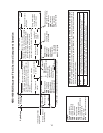
B. Wiring Diagrams ......................................................................................................... 8
1. KMS-1400MLH – SRK-14H ................................................................................... 8
. KMS-1400MLH – SRK-14H3 ................................................................................. 9
3. Wire Harness Connections .................................................................................... 30
C. Performance Data ...................................................................................................... 31
1. KMS-1400MLH – SRK-14H ................................................................................... 31
. KMS-1400MLH – SRK-14H3 ................................................................................. 3
IV. Service Diagnosis .......................................................................................................... 33
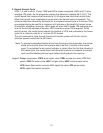
A. 10-Minute Diagnostic Procedure ................................................................................ 33
B. Diagnostic Charts ....................................................................................................... 36
1. No Ice Production .................................................................................................. 36
. Evaporator is Frozen Up ....................................................................................... 39
3. Low Ice Production ................................................................................................ 40
4. Abnormal Ice ......................................................................................................... 40
5. Other ..................................................................................................................... 40
V. Removal and Replacement of Components ................................................................... 41
A. Service for Refrigerant Lines ...................................................................................... 41
1. Refrigerant Recovery ............................................................................................ 41
. Brazing. ................................................................................................................. 4
3. Evacuation and Recharge (R-404A) ..................................................................... 4
B. Condensing Unit ......................................................................................................... 43
1. Removal and Replacement of Compressor .......................................................... 43
. Removal and Replacement of Condenser ........................................................... 44
3. Removal and Replacement of Hot Gas Valve and Liquid Line Valve ................... 45
4. Removal and Replacement of Headmaster ......................................................... 46
5. Removal and Replacement of Fan Motor .............................................................. 46
C. Icemaker .................................................................................................................... 47
1. Removal and Replacement of Evaporator ............................................................ 47
. Removal and Replacement of Expansion Valve ................................................... 48
3. Removal and Replacement of Hot Gas Valve and Liquid Line Valve ................... 49
4. Removal and Replacement of Pump Motor .......................................................... 50
5. Removal and Replacement of Fill and Harvest Water Valve ................................ 50
6. Removal and Replacement of Thermistor ............................................................. 51