


1
B. Sequence of Operation
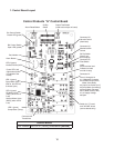
The steps in the sequence are as outlined below. When power is supplied, the red
POWER OK LED and the green BC CLOSED LED on the control board come on (If the
yellow BC OPEN LED is on, the unit will not start. In this case clear ice away from the
bin control actuator in the bin area). A 5-second delay occurs at startup. Note that the
order of the green sequence LEDs from the outer edge of the board is 1, 4, 3, .
1. One Minute Fill Cycle
LED 4 is on. FWV opens and the ll period begins. After 1 minute, the board checks
for a closed LF/S. If LF/S is closed, the harvest cycle begins. If not, FWV will remain
energized through additional 1 minute cycles until water enters the sump and LF/S
closes. This serves as a low water safety to protect the water pump.
2. Initial Harvest Cycle
LEDs 1, 4 and are on. Comp, FMR, HGVs, HWV and X1 relay energize, FWV closes.
The control board monitors the warming of the evaporator via the thermistor located
on the suction line. When the thermistor reaches 48°F (9°C), the control board reads a
3.9 kΩ signal from the thermistor and turns harvest termination over to the adjustable
harvest timer which is factory set for normal conditions. The timer has settings of 60,
90, 10, and 180 seconds (S4 dip switch 1 & ). When the harvest timer completes its
count down, the harvest cycle is complete and the freeze cycle starts. The minimum
total time allowed by the board for a complete harvest cycle is minutes. HWV is open
during harvest for a maximum of 6 minutes or the length of harvest minus 50 seconds,
whichever is shorter. LED 4 goes off when HWV closes. PM energizes and runs for the
last 50 seconds of harvest. LED 3 comes on when PM energizes. At the end of harvest,
the control board checks the position of LF/S and proceeds to the freeze cycle if it is
closed or calls for a 1-minute ll if it is open.
3. Freeze Cycle
LED 1 is on. Comp, FMR and PM continue to run, LLVs open, HGVs close. For the rst
5 minutes, the control board will not terminate the freeze cycle. As ice builds and LF/S
opens, FWV opens (LED 4 is on when FWV is open). The rell will last until U/FS closes
or for 60 seconds, whichever is shorter. After UF/S closes, FWV closes 3 seconds later.
The KMS-1400MLH rells 1 time. After the rell, the freeze continues until LF/S opens
again. The freeze cycle is then terminated, provided the 5 minute freeze timer has
expired.
4. Pump-Out Cycle
The 1st pump out occurs after the 11th freeze cycle and every 10th cycle thereafter.
LEDs 1, 3, and are on. Comp and FMR continue to run, DWV opens, HGVs open,
LLVs close. PM stops for seconds. PM restarts, pumping water from the water tank
through the DWV and down the drain. At the same time, water ows through the vent
tube to power ush the F/S. After 10 seconds, the pump out is complete. The pump-out
frequency control is factory-adjusted to drain the water tank every 10 cycles, and no
adjustment is required. However, where water quality is bad and the icemaker needs a
pump out more often, the pump-out frequency can be adjusted. See "II.C.3.d) Pump-Out
Frequency Control."