


3
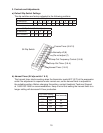
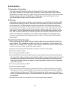
E. Float Switch
1. Explanation of Operation
The oat operates switches within the oat switch. The lower switch (black and
blue wires) is used for low water safety protection, initiating the freeze cycle rell and
terminating the freeze cycle. The upper switch (black and red wires) is used to terminate
the freeze cycle rell only. Rell will last until the upper oat switch closes or the 1
minute countdown timer ends, whichever comes rst.
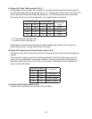
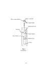
2. Cleaning
Depending on local water conditions, scale may build up on the oat, oat switch shaft
and inside the housing. Scale on the oat or shaft can cause the oat to stick causing
erratic operation. The oat switch should be cleaned and checked before replacing.
First, disconnect the black K5 oat switch connector from the control board and remove
the oat switch and rubber boot from the icemaker. Remove the rubber boot from the
oat switch. Twist the mechanical lock at the top of the oat housing and lower out the
oat and oat shaft. Remove the retainer clip from the shaft and slide the oat off the
shaft. Soak the switch assembly in ice machine cleaner. Wipe down the shaft, oat,
housing, and rubber boot with cleaning solution. See "VI. Cleaning and Maintenance
Instructions."
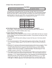
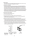
3. Float Switch Check Procedure
Before replacing a oat switch that you suspect is bad, make sure the oat switch has
been cleaned. This procedure will help you verify your diagnosis. The oat switch has
three wires. The black wire is common. The blue wire is for the lower oat switch contact
and the red wire is for the upper oat switch contact.
1) Disconnect the black K5 oat switch connector from the control board.
) Drain the reservoir water.
3) Turn the control switch to "ICE".
4) As water lls the reservoir, the oat switch contacts should close. Check continuity of
the lower oat switch contacts using the black and blue wires and the upper oat switch
contacts using the black and red wires. With the oat positioned all the way up, both
oat switch contacts should be closed. If either oat switch contact fails, the assembly
should be replaced.
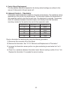
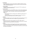
5) Turn the control switch to "OFF".
6) Drain the reservoir water.
7) As water drains, the oat switch contacts should open. Check continuity of the upper
oat switch contacts using the black and red wires and the lower oat switch contacts
using the black and blue wires. With the oat positioned all the way down, both oat
switch contacts should be open. If either oat switch contact fails, the assembly should
be replaced.
8) Reconnect the black K5 connector to the control board when nished.