


1
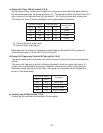
f) Freeze Timer (S4 dip switch 9 & 10)
CAUTION
Adjust to proper specication, or the unit may not operate correctly.
The freeze timer setting determines the maximum allowed freeze time to prevent
possible freeze-up issues. Upon termination of freeze timer, the control board initiates
the harvest cycle. After consecutive timer terminations, the control board shuts the
machine down. In this case, see "IV.B.3. Low Ice Production" for possible solutions.
The freeze timer is factory adjusted and no adjustment is required.
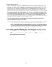
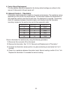
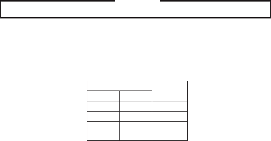
Dip Switch Setting
Time
(minutes)
No. 9 No. 10
OFF OFF 60
OFF ON 50
ON OFF 70
ON ON 60
g) Float Switch Control and Refill Counter (S5 dip switch 1 through 5)
Do not adjust. These must be left in the factory default position or the unit will not
operate properly. The KMS-1400MLH rells 1 time.
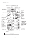
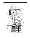
4. Control Board Check Procedure
Before replacing a control board that does not show a visible defect and that you suspect
is bad, always conduct the following check procedure. This procedure will help you verify
your diagnosis.
1) Check the S4 and S5 dip switch settings to assure that they are in the factory default
positions.
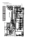
) Turn the control switch to "ICE" and check for proper control voltage. If the red LED
is on, the control voltage is good. If the red LED is off, check the control transformer
circuit.
3) Check the 115 volt input at the wire harness terminals and the 10-pin connector. Check
the brown and white wire at pin #10 to a white neutral wire for 115 volts. (Always
choose a white neutral wire to establish a good neutral connection when checking
voltages.) On the 10 pin connector, a jumper also feeds 115 volts into pin #7. If no
voltage is present, check the 115 volt supply circuit.
4) The output test button provides a relay sequence test. Make sure the control switch is
in the "ICE" position, then press the output test button. The correct lighting sequence
should be 1, 4, 3, . Some components (e.g., the compressor) will cycle during the test.
Note that the order of the relays from the outer edge of the board is 1, 4, 3, . After
checking the sequence, the unit automatically starts at the 1 minute ll cycle. If the
LEDs light in a different sequence, the control board is bad and should be replaced.