


34
5) Freeze Cycle – LED 1 is on. The compressor, fan motors and pump motor remain
energized. The liquid line valves energize and the hot gas valves de-energize (also
de-energizing the X1 relay). The lower oat switch activates (open) times during
the course of a freeze cycle; the rst is for rell, the second is for freeze termination.
After the second lower oat switch activation, the control board terminates freeze and
initiates harvest. Every 10th cycle, the control board initiates a 10 second pump-out
cycle between the freeze and harvest cycles. See "II.C.3.d) Pump-Out Frequency
Control."
a. Lower Float Switch 1st Activation: Rell – LEDs 1 and 4 are on. The rell can occur
at any time during the freeze cycle (1 rell per cycle). As ice builds the water level
drops in the reservoir and the lower oat switch activates (opens). LED 4 comes on and
the control board energizes the ll water valve. The ll water valve remains energized
until the upper oat switch closes or the 1 minute ll timer terminates, whichever comes
rst.
b. Lower Float Switch 2nd Activation: LED 1 is on. The unit is held in freeze by a
5 minute short cycle protection timer. After the 1st lower oat switch activation and
rell, ice continues to form and the water level drops in the reservoir. When the lower
oat switch activates (opens) a second time, the freeze cycle terminates (freeze
can only be terminated on the second activation of the lower oat switch and after
5 minutes of freeze). Diagnosis: Minimum freeze time is 5 minutes. During the rst
5 minutes of freeze, conrm that the evaporator temperature drops, compressor, fan
motors, pump motor, and liquid line valves are energized and that the hot gas valves,
harvest water valve and ll water valve (except during rell) are de-energized and
not bypassing. Make sure the expansion valves are operating properly and, in cold
conditions, make sure the headmaster (C.P. Regulator) is operating correctly. Make
sure that the drain water valve is not leaking by (water owing down the potable drain).
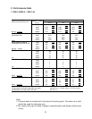
Check for proper unit pressures (see "III.C. Performance Data"), or an inoperative
compressor. Disconnect the black K5 oat switch connector from the control board.
15 seconds after disconnecting the black K5 oat switch connector, LED 4 comes
on and rell begins. Connect the black K5 oat switch connector back on the control
board. When the rell is nished (LED 4 goes off), disconnect the black K5 oat switch
connector again. If 5 or more minutes have elapsed in the freeze cycle, the unit should
switch out of the freeze cycle. After the unit switches out of freeze, reconnect the black
K5 oat switch connector to the control board. If the unit remains in freeze with the oat
switch disconnected, replace the board. To check the oat switch, see "II.F.3. Float
Switch Check Procedure."
Note: Normal freeze cycle will last 30 to 35 minutes depending on model and
conditions. Cycle times and pressures should follow performance data provided
in this manual.