


16
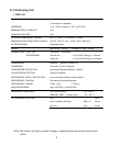
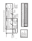
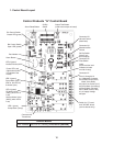
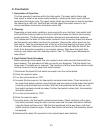
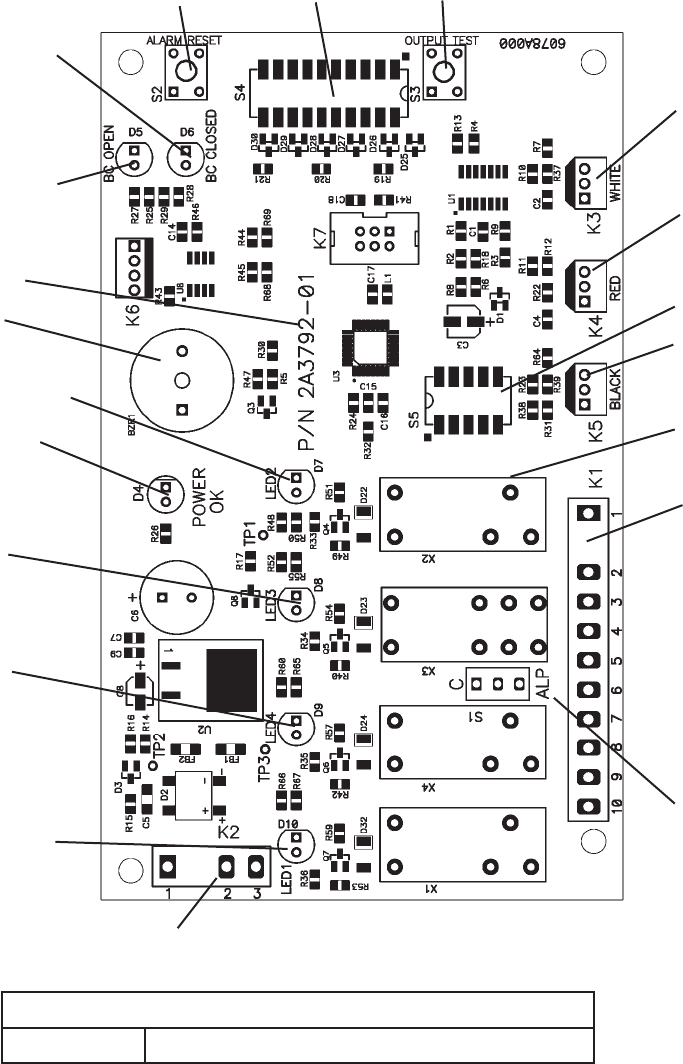
1. Control Board Layout
Control Board
Part Number A379-01 (factory); 2A3792-02 (service)
Control Products "G" Control Board
Alarm Reset Button
Output Test Button
(used to test relays on board)
Connector K3
Harvest Control
(thermistor)
Connector K4
Mechanical Bin
Control
Label
(board revision level
indicated on label
on side of relay)
Connector K5
Float Switch
Part Number
Connector K1
Pins #1 through #10
#1, 9 Magnetic Contactor
# Hot Gas Valves (HGV)
Water Valve Relay
#3 Liquid Line Valves (LLV)
#4 Pump Motor (icemaking)
#5 Pump Motor (harvest)
#6 Fill Water Valve (FWV)
#7 10 Supply Voltage
#8 Open
Switch for "C" board
and "ALPINE" board
(service boards only)
Bin Control Switch
Open LED (yellow)
S4 Dip
Switch
Bin Control Switch
Closed LED (green)
Alarm Buzzer
Power LED (red)
(lights when power
is supplied to the
board)
LED (green)
Hot Gas Valves (HGV)
LED 3 (green)
Pump Motor (PM)
(PM on, but LED off,
at freeze cycle)
LED 4 (green)
Fill Water Valve
(FWV) (when LED
is off)
Harvest Water Valve
(HWV) (when LED
is on)
LED 1 (green)
Compressor (Comp)
Connector K
Transformer
S5 Dip Switch
(factory set -
do not adjust)