84
Appendix 10 WIRING DIAGRAMS
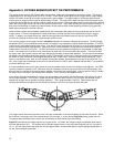
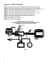
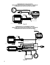
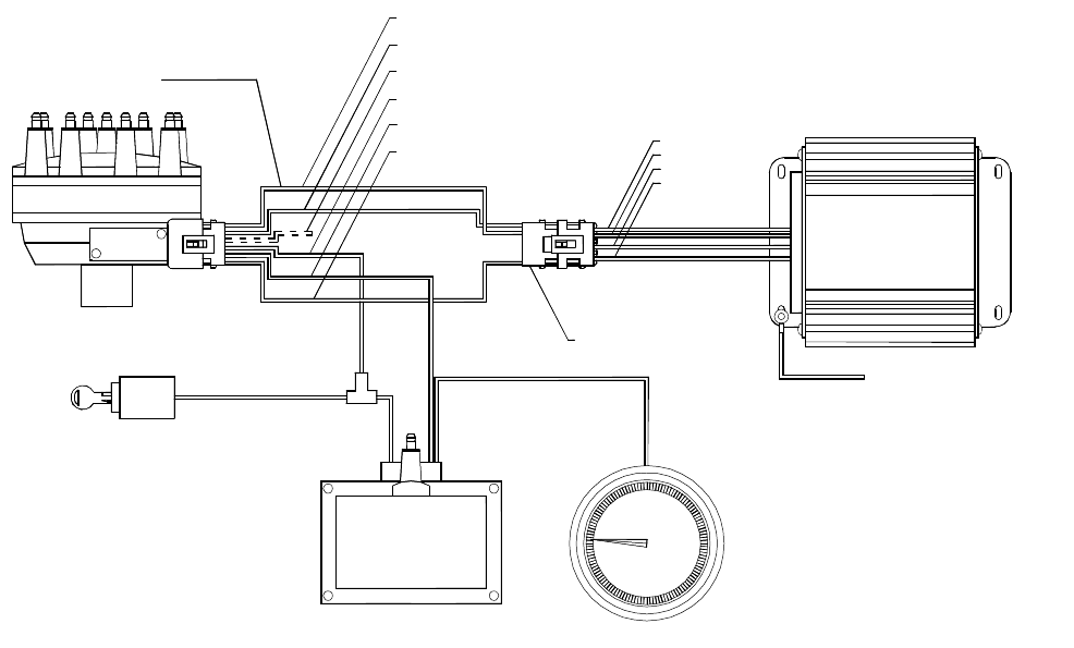
Figure 61: Commander 950 to Ford TFI Ignition Using Ford Computer Controlled Distributor, TFI Module.
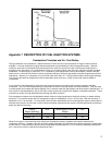
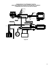
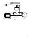
Figure 62: Commander 950 to Aftermarket Ignition Using Ford Computer Controlled Distributor, TFI Module.
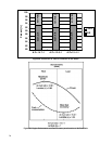
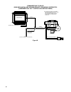
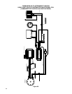
Figure 63: Commander 950 to GM HEI Using Mechanical and Vacuum Advance 4-Pin Module Distributor.
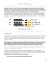
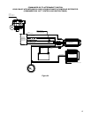
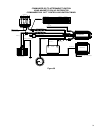
Figure 64: Commander 950 to Aftermarket Ignition Using GM HEI with Mechanical Advance 4-Pin Module Distributor.
Figure 65: Commander 950 to GM HEI Using Computer Controlled Distributor, 7-Pin Module.
Figure 66: Commander 950 to Aftermarket Ignition Using Computer Controlled Distributor, 7-Pin Module.
Figure 67: Commander 950 to GM HEI Using Computer Controlled Distributor, External Coil.
Figure 68: Commander 950 to Aftermarket Ignition Using a GM 7-Pin Style Distributor and External Coil.
Figure 69: Commander 950 to Aftermarket Ignition Using Magnetic Pick-up Distributor.
Figure 70: Commander 950 to Aftermarket Ignition Using Magnetic Pick-up Crank Trigger.
Figure 71: Commander 950 to Aftermarket Ignition Using Hall Effect Pick-up Crank Trigger.
Figure 72: GM TPI Engines—P/N 271R865A
Figure 73: Holley SBC & BBC MPFI—P/N 271R875A
Figure 74: Holley 4 BBL TBI—P/N 271R884A
Figure 75: GM LT1/LT4 Engine—P/N 271R886A
COMMANDER 950 TO FORD TFI IGNITION
USING FORD COMPUTER-CONTROLLED DISTRIBUTOR, TFI MODULE
(COMMANDER 950 CONTROLLING IGNITION TIMING)
COMMANDER 950
BLUE/WHITE
YELLOW/BLACK
TAN/BLACK
BLACK (16 AWG)
DISTRIBUTOR
GROUND CASE TO ENGINE BLOCK
5
TACHOMETER
0
2
1
3
4
RPM
10
9
7
6
8
(PIP) YELLOW/BLACK
(SPOUT) BLUE/WHITE
(START) PIN NOT USED
(POWER) RED
(TACH) RED/WHITE
(GROUND) BLACK
(+) SWITCHED POWER
SWITCH
IGNITION
(+)
HOLLEY 820-211
INDUCTIVE COIL
(-)
4-PIN PIGTAIL CONNECTOR
HARNESS P/N
534-139
Figure 61


