5
Appendix 7 covers the description of fuel injection systems, including: combustion principles and air/fuel ratios, emissions
and performance, and engine management systems. These engine management systems consist of: air management, fuel
management, and ignition timing management.
Appendix 8 covers the engine application and the selection of your fuel management system components, including: injector
fuel flow and fuel pressure.
Appendix 9 covers the two kinds of fuel pumps and their flow characteristics.
Appendix 10 shows the many wiring diagrams needed to install your Commander 950 fuel injection system.
1.0 TERMS & DEFINITIONS OF FUEL INJECTION MANAGEMENT SYSTEMS
1.1 Fuel Management System
Fuel management systems comprise a selection of components and assemblies whose main function is to supply a mixture of
fuel and air to the engine in proportions such that it will be easily ignited by the spark. In a carbureted system the main
components are the carburetor and the mechanical fuel pump. In fuel injection systems the main components are the fuel
injectors, the air valve, the electric fuel pump, and the Engine Control Unit (ECU). The fuel pump’s main function is to supply
fuel to the metering unit: carburetor or fuel injectors. Airflow is adjusted by the air valve. In carburetors the air valve is part of
the carburetor. In fuel injection systems the air valve is part of the metering system, such in the case of the Throttle Body
Injection systems (TBI systems), or is separate from the fuel metering system as in the Multi-Point Fuel Injection (MPFI
systems). In fuel injection systems, the ECU is the computer that controls the fuel metering function of the fuel injectors
according to the input of the sensors. In the carburetor the jets and the vacuum regulated by the air valve control the fuel
metering function.
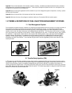
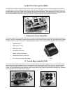
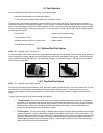
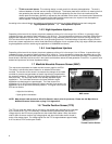
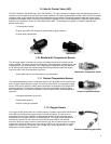
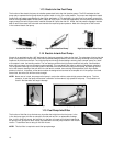
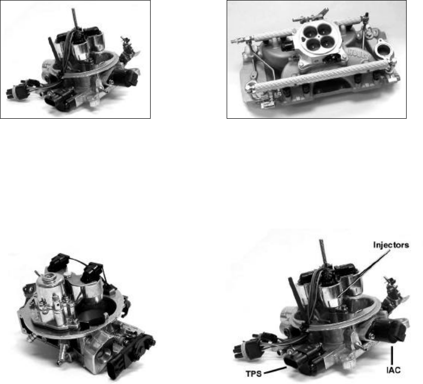
Throttle Body Injection (TBI) Multi-Port Fuel Injection (MPFI)
1.2 Throttle Body Injection (TBI)
In TBI systems, the throttle body assembly has two major functions: regulate the airflow and house the fuel injectors and the
fuel pressure regulator. The choices of throttle bodies range from single barrel/single injector unit generally sized for less than
150 HP to four barrel/four injector unit capable of supporting fuel and air flow for 600 HP The injectors are located in an
injector pod above the throttle valves. The quantity of fuel the injector spray into the intake manifold is continuously controlled
by the ECU. Most of the TBI systems use bottom fed fuel injectors. The injector spray pattern is designed to allow fuel to pass
between the throttle valve and the throttle bore.


