17
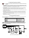
5.1 Step-by-Step Wiring Harness Installation
NOTE: It is advised to leave the battery completely disconnected until the installation of the entire system is
completed.
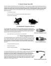
1. ECU MOUNTING – The ECU should be mounted as far away from the ignition box as is feasible (minimum 6”). The ECU
must be installed in the vehicle in a location free from moisture and dirt. The glove box area is usually a good location in
most vehicles. There are sheet metal screws included for this purpose. The ECU must be grounded. If you mount it on a
non-metallic surface (ex. fiberglass body), run a 14 gauge ground wire to the chassis.
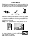
2. WIRING HARNESS - The wiring harness will need to be fed through the firewall in the vehicle. Drill a 2 inch diameter
hole and feed the harness through it. A grommet is provided for this hole so the harness will not be damaged. Be very
careful that the hole you drill does not interfere with items like wiring harnesses, heating, or AC systems.
3. CONNECT WIRING HARNESS - After the harness is routed through the hole connect it to the ECU. Route the rest of the
harness into the engine compartment.
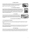
4. INSTALL RELAY - A system power relay is included. The relay holder for it is about 3 feet from the ECU connection.
The relay can be mounted inside the interior or in the engine compartment. Decide where you want it and secure the
relay. A sheet metal screw is provided for this purpose. Be careful that you don’t drill through the firewall and damage
something. Mount the relay and attach it to the harness.
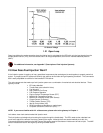
5. INSTALL FUSE - The 15 amp fuse needs to be installed in the fuse holder. The fuse is included and the fuse holder is
located near the ECU. Install it now.
5.2 Non-Terminated Wire Connection
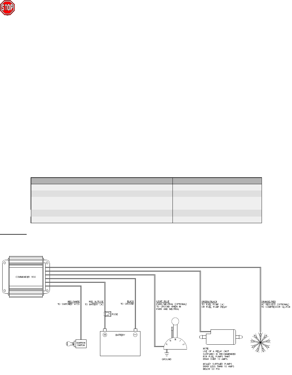
Next, the non-terminated wires will be connected (Figure 3). The following chart provides an overview. However, each one
will be described separately.
NON-TERMINATED WIRE COLOR AND DESCRIPTION WIRE CONNECTION LOCATION
Black
Ground connection
Red with fuse
12 Volt - attach to the battery
Red/White
Switched +12 volt power
Orange/Red
AC Request (Optional) +12v
Light Blue
Park/Neutral (Optional) Ground
Green/Black
+ 12 volt Fuel Pump
WARNING! Keep all wires away from hot exhaust components. Bare or frayed wires can result in electrical short
Circuits, which can cause system or vehicle damage, or a fire hazard resulting in property damage,
serious injury, and/or death.
Figure 3 Non-Terminated Wiring Diagram


