76
Appendix 6 OXYGEN SENSOR EFFECT ON PERFORMANCE
The oxygen sensor monitors the exhaust gases and outputs a voltage that corresponds to the air/fuel mixture. The range of
voltage output from the oxygen sensor is 0.0 to 1.0 volts. A lean fuel/air mixture gives a lower oxygen sensor output voltage
while a rich fuel/air mixture gives a higher oxygen sensor output voltage. The stoichiometric or chemically perfect fuel/air
mixture gives an oxygen sensor output of approximately 0.5 volts. The engine ECU reads this output from the oxygen sensor
and adjusts the fuel delivery to maintain a stoichiometric air/fuel mixture. Most automobiles, both currently and for the past 20
years, are using oxygen sensors to monitor the engine fuel/air mixture. This is done primarily to improve engine emissions. It
also gives the advantage of maintaining a stoichiometric air/fuel mixture under varied operating conditions giving generally
better engine performance and fuel economy.
Holley includes oxygen sensor feedback capability with the Commander 950 system and recommends the user to use the
oxygen sensor. For most user applications, better performance and fuel economy will be obtained by using the oxygen
sensor. In addition, the oxygen sensor can make the tuning process much easier since the user can monitor the ECU
functions as it adjusts the fuel to meet a stoichiometric fuel/air mixture.
The mounting location of the oxygen sensor is extremely important for the proper operation of the engine. The exhaust gas
temperature (EGT) in the exhaust where the sensor is mounted is very important for proper closed loop operation. If the EGT
is too low, two undesirable conditions can result. First, the ECU may sense that the O
2
sensor is not up to proper temperature
and will not activate closed loop operation. Second and much more troublesome, is that the sensor could emit a false low
voltage even if the air/fuel ratio is rich. The ECU will see this as a lean condition and add fuel to compensate in closed loop
mode. This makes the rich condition even worse which will lower the EGT and complicate the problem. The lower the EGT
the sensor sees, the slower the sensor will react, reducing the benefits of closed loop operation. The minimum recommended
temperature for reasonable closed loop operation is 600° F (Fahrenheit) at the sensor. Maximum continuous temperature at
the sensor is 1500° Fahrenheit. Most engines idle with an EGT of 800-1100° F near the cylinder head exhaust port. If the
sensor is mounted far away, such as in the collector of long tube headers, the temperature may drop to as low as 300° F at
idle. If the oxygen sensor attempts to control the air/fuel ratio when the EGT it sees is between 300 and 600° F, the problems
mentioned above can occur.
It is recommended to mount the oxygen sensor as close as possible where one bank of cylinders merge together. If an OEM
mounting location is available, use it. With stock cast iron manifolds, the sensor can be mounted in the exhaust pipe, right
after the cast iron manifold in the exhaust pipe or possibly in the end of the manifold itself. If the vehicle has “shorty” headers,
the sensor can be mounted in the collector of the headers. This is usually an acceptable location.
If the vehicle has long tube headers, the sensor can be mounted in the collector, but the temperature will likely be too low at
idle for proper operation. A fix for this, if proper closed loop operation does not occur, is to run open loop at lower engine
speeds until enough heat is available for proper operation. This is programmable in the ECU. Other factors such as
camshaft specifications will effect how well closed loop operation occurs at low engine speeds and loads.
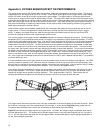
Figure 56
The oxygen sensor should be mounted in such a way the condensation in the exhaust tubing will not enter the sensor. Mount
the O
2
sensor in the upper half of the exhaust tubing, with the angle “x”, shown above (Figure 56), being greater than 10°.
The picture above indicates that the sensor can be mounted on either side of the exhaust tubing.
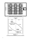
Figure 57 below shows the voltage output of an oxygen sensor. As shown, the voltage changes considerably when the air /
fuel ratio approaches 14.7:1. This explains why a standard oxygen sensor is only accurate at signifying an air / fuel ratio of
14.7:1. Air / fuel ratios richer and leaner can only be approximated. As discussed above, if the exhaust gas temperature is
too low, these readings will be false.


