64
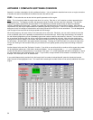
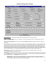
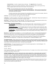
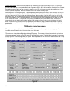
Inductive Pickup – Use with a magnetic pickup crank trigger. See Appendix 10 for wiring specifics.
Ford TFI – Use with Ford TFI electronic distributors. Allows for the Commander 950 to control ignition timing.
Requires adapter cable PN 534-139, which is included in Ford 5.0L MPFI kits.
GM HEI – If any of the following ignition systems are used, select GM HEI.
- 1981 and up GM small and large cap computer controlled HEI distributors. Allows for the Commander 950 to
control timing. Adapter PN 534-138 is needed with small cap distributors. It is included with all Holley small
and big block Chevy MPFI systems.
- CD ignition system with a fixed timing (typical with race applications) point (such as 36° for example). When the
tach output from the CD ignition system will be used to trigger the fuel system.
Hall Effect – Use with a Hall Effect crank trigger of Hall Effect Distributor.
Load Sense – The ECU can operate in either Alpha-N or Speed-Density mode. Speed density is always used if possible, but
for applications with low manifold vacuum, Alpha-N is most likely needed.
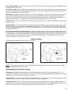
Fan Control – The 950 can control an external cooling fan. The user can set the on and off temperatures for this fan so the
coolant temperature is better maintained. Relay kit PN 534-134 is needed for this feature.
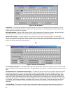
Throttle Sensor – Adjust the following settings
- WOT TPS Position – Enter the position of the TPS at wide-open throttle. Do this with the key “on” and engine
not running. Look at the data monitor in the main fuel map for this value. Reset if the throttle position is
changed at idle.
- Clear Flood TPS Position – At a TPS position higher than this value, the ECU will not add cranking fuel. Make
this number about 50 lower than the WOT TPS Position. If the engine is flooded when it is started, depress the
pedal past the Clear Flood TPS Position.
- TPS Noise Value – This value corresponds to how much of a throttle change needs to be made before the ECU
detects it as having changed and not just electrical “noise” having caused a sensor change. Numbers of 1 or 2
should be fine.
Map Sensor – The ECU can be connected to a 1, 2, or 3 bar manifold pressure sensor. All naturally aspirated applications
will use a 1 bar MAP sensor. The 2 and 3 bar map sensors would be used in supercharged or turbocharged applications
where a two bar sensor is good for up to 15 pounds of boost and a 3 bar sensor is good for up to 30 pounds of boost.
Map Noise value – This value is very similar to the TPS noise value, except that it corresponds to the manifold pressure
sensor instead of the throttle sensor. The base value of 3 should work fine. It should be set between 1 and 3.
Fuel pump prime time – When the key is first turned to the on position, the system will energize the fuel pump to pressurize
the system. The ECU will not allow the pump to run longer than this much time if the engine is not started. Naturally, as soon
as the engine is started, the fuel pump will turn on and remain on until the triggers stop. This number can be raised if the fuel
system takes an abnormally long time to prime. 5 seconds should be adequate.
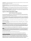
Ignition Reference – This angle corresponds to the position of the ignition-triggering device in crankshaft degrees. The
following are guidelines for different ignition systems:
GM HEI – Set to 10
Ford TFI – Set to 10
Crank Trigger and Hall Effect – Set 10 HIGHER than the maximum timing. For example, if you will have a maximum timing of
42 degrees, set the Ignition Reference to 52.
Ignition propagation delay – All ignition modules have some amount of delay built in. This parameter will compensate for
this delay. If this delay is not correct, the timing light will show a timing advance or retard with engine speed, even if the
timing curve is “flat”. This value should be set so that the actual timing is correct at all RPMs. Usually the base value of 48
usec is fine. If the rpm is raised and the actual timing (as measured with a timing light) is less than the desired (as shown on
the laptop), increase the propagation delay until the actual timing matches the desired. If the actual timing is more than the
desired, decrease the propagation delay. Make changes in units of 20 usec.
Timing advance while cranking – This is the amount of timing the ECU will give when the engine is trying to start. This is
only active when the Inductive or Hall Effect Settings are used. If HEI or TFI is used, the timing during cranking will be the
same as the base module timing below 400 rpm.


