


GPSMAP
®
400 Series Owner’s Manual 49
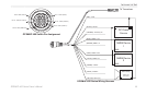
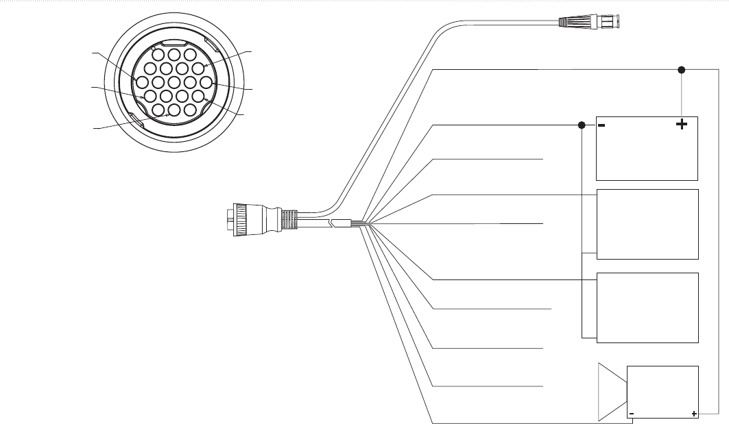
InStallInG the unIt
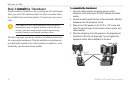
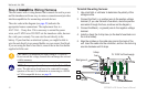
DC Power
Source
NMEA Device
1
NMEA Device
2
RXD+
RXD-
RXD+
RXD-
(RED) +VDC
(BLACK) Ground
(ORANGE) Accessory On
(BLUE) NMEA 1 Out
(BROWN) NMEA 1 In
(GREY) NMEA 2 Out
(GREEN) CANet L
(WHITE) CANet H
(YELLOW) Alarm Low
(VIOLET) NMEA 2 In
Alarm Relay
100ma max
coil current
To Transducer
GPSMAP 400 Series Wiring Harness
PIN 8 - Black (Ground)
PIN 13 - Red (DC Positive)
PIN 7 - Yellow (Alarm)
PIN 12 - White (CANet H)
PIN 16 - Green (CANet L)
PIN 18 - Blue (NMEA Out)
GPSMAP 400 Series Pin Assignment