


48 GPSMAP
®
400 Series Owner’s Manual
InStallInG the unIt
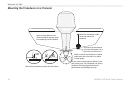
Step 4: InstallInstall the Wiring Harness
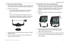
The unit comes with a wiring harness that connects the unit to power
and the transducer with one easy-to-remove connection and provides
interface capabilities for connecting external devices.
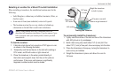
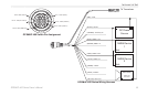
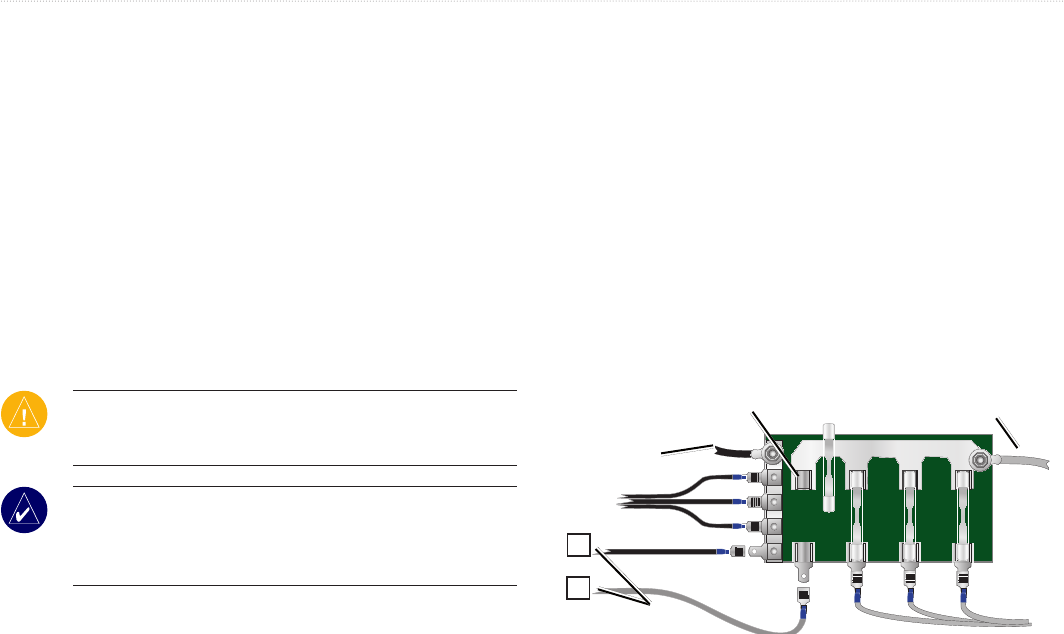
The color code in the diagram (see page 49) indicates the
appropriate harness connections. The replacement fuse is a
AGC/ 3AG - 3 Amp fuse. If it is necessary to extend the power
wires, use 22 AWG wire. DO NOT cut the transducer cable, because
this voids your warranty. You can wire the unit directly to the
battery. If your boat has an electrical system, you might be able to
wire the unit directly to an unused holder on your current fuse block.
If you are using the boat’s fuse block, remove the in-line fuse holder
supplied with the unit.
CAUTION: The maximum unit input voltage is 35-Volts DC.
Do not exceed this voltage, because this can damage the unit and
void the warranty.
NOTE: During a typical installation, use only the Red and Black
wires. The other wires do not have to be connected for normal
operation of the unit. For information on connecting to a NMEA
or CANet compatible device, see page 50.
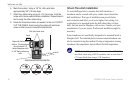
To install the wiring harness:
1. Use a test light or voltmeter to determine the polarity of the
voltage source.
2. Connect the Red (+ or positive) wire to the positive voltage
terminal. (If you use the boat’s fuse block, route the positive
connection through the fuse, as shown on the diagram.)
3. Connect the Black (- or ground) wire to the negative voltage
terminal.
4. Install or check the 3-Amp fuse (on the boat’s fuse block or in
the in-line holder).
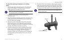
5. Align the notches on the cable plug and on the back of the
unit. Insert the cable into the connector, and turn the lock ring
counter-clockwise until it stops.
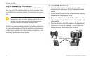
—
+
To 10-35 Volt boat supply
2A
3A
-
+
Boat ground
3-Amp
fuse
To Unit
Fuse block