


46 GPSMAP
®
400 Series Owner’s Manual
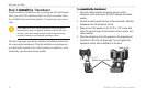
InStallInG the unIt
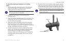
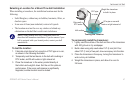
6. Mark the location. Using a 1/8" bit, drill a pilot hole
approximately 3/8" (10 mm) deep.
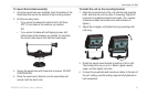
7. Attach the cable clamp using a 4 x 12 mm screw. Coat the
screw with marine sealant before installation. Repeat steps 5
and 6 using the other cable clamp.
8. Route the transducer cable, as needed, to the unit. DO NOT
CUT THE CABLE. Avoid routing the cable with electrical
wires or other sources of electrical interference.
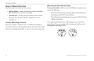
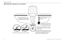
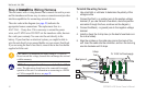
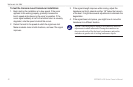
OK
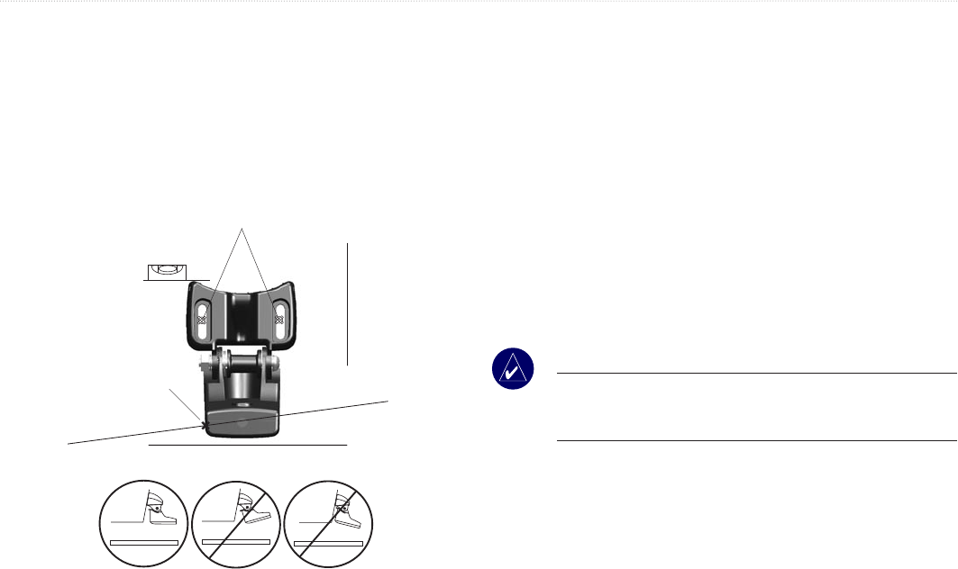
Level
Drill pilot holes here.
Vertical
Bottom of the transom
Align with the transom
bottom. The transducer
should extend 1/8"
below berglass hulls
or 3/8" below aluminum
hulls.
Keep it parallel with the water line.
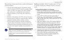
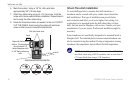
Shoot-Thru-Hull Installation
To avoid drilling a hole to mount a thru-hull transducer, a
transducer can be secured with epoxy inside a boat (shoot-thru-
hull installation). This type of installation can provide better
noise reduction and allow you to use a higher Gain setting. For
a transducer to be mounted inside the hull (shoot-thru, not thru-
hull),theboatmustbeberglass,withnocore.Contactyourboat
manufacturer if you are unsure. Professional installation might be
necessary.
Sometransducersarespecicallydesignedtobemountedinsidea
berglasshull.Thestandardplastictransommounttransducercan
also be mounted using this method. If using a temperature sensing
transducer,thetemperatureshownreectsthehulltemperature.
NOTE: Asolidberglasshullcanbenomorethan5/8"(9.53
mm) thick when using a 500 W transducer, and no more than 1"
(25.4 mm) thick when using a 1 kW transducer.