


9. INSTALLATION
9-6
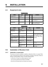
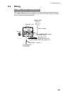
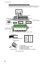
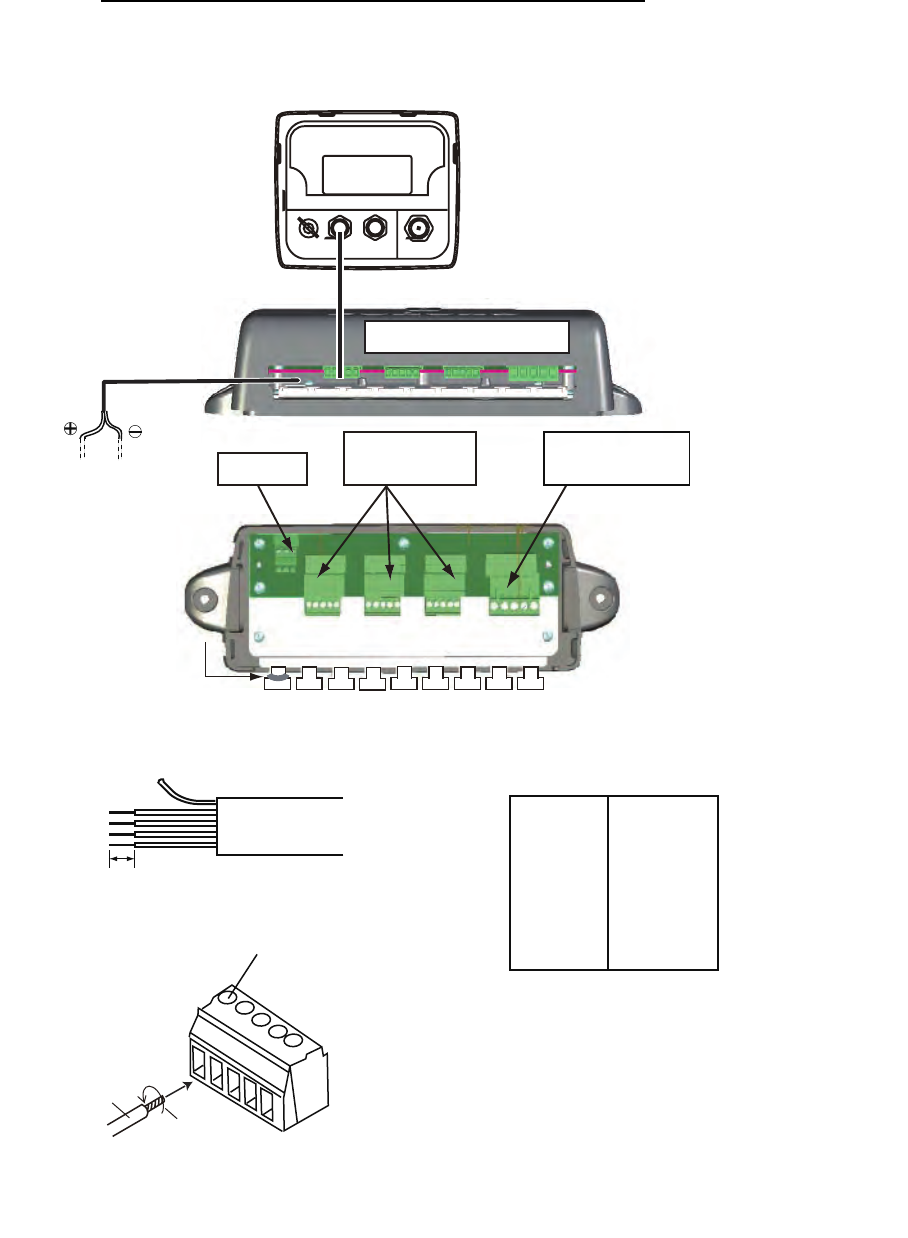
Connection with the optional junction box FI-5002
Detailed information for the service technician about CAN bus wiring is in the docu-
ment titled “Furuno CAN bus Network Design Guide (TIE-00170-*)” separately.
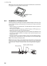
• Fabrication of M12-05BM+05BF-060 cable and MC connector
12VDC
CN3 - CN5
DROP
FI-5002 (option)
Power cable (2m)
M12-05BM+05BF-060
(6 m)
to switchboard
(12 VDC)
CN2
BACKBONE
MC connector
White
Black
Fix cable with
cable tie (supplied).
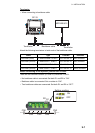
Top view
Side view
Use CN2 to CN5.
MC connector
6 mm
1. Twist wires.
2. Loosen fixing screw in plug.
3. Insert wire into hole.
4. Tighten fixing screw.
5. Pull wire to confirm the connection.
#1
#2
#3
#4
#5
Drain
Red
Black
White
Blue
Drain wire
Fixing screw
How to fabricate cable
How to insert wire