


Copyright 2009 Firstech, LLC.
Page 17
CM6200 Install Guide
Starter System
www.firstechonline.com | www.compustar.com
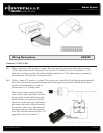
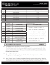
Connector 5 (CN5), 4-Pin (RS 232 Data Port)
This connector is used for updating control modules via www.rstechonline.com. You must also use this port to
ash Blade bypass modules. This port provides simple connectivity of Fortin and iDataLink bypass modules.
Connector 6 (CN6), 4-Pin D.A.S. Sensor Input
For future use: This connector is designed for used with the Firstech D.A.S sensor. This is an optional input
for use with the upcoming D.A.S sensor. It will detect movement of the vehicle in failsafe with the reservation
mode.
Connector 7 (CN7), 4-Pin to 4-Pin or 6-Pin (Pre-wired Antenna Cable)
Connect your antenna cable to this port. You can only use 4 to 4 pin or 4 to 6 pin antenna cables. 6 to 6 Pin an-
tenna cables do not work. Do not use both Connector 9 and Connector 10 at the same time.
Pin 1 Yellow - RX input. This wire receives the signal from remote.
Pin 2 White - TX output. This wire transmits the signal to remote.
Pin 3 Red – Constant 12V positive (+) output.
Connector 8 (CN8), 6-Pin to 6-Pin (Pre-wired Antenna Cable)
Connect your antenna cable to this port. You can only use 6 to 6 pin antenna cables. 4 to 4 or 4 to 6 Pin antenna
cables do not work. Do not use both Connector 9 and Connector 10 at the same time.
Pin 1 Yellow - RX input. This wire receives the signal from remote.
Pin 2 White - TX output. This wire transmits the signal to remote.
Pin 3 Red – Constant 12V positive (+) output.
Pin 4 Black – Negative (-) ground.
Connector 9 (CN9), 2-Pin (Pre-wired Thermister)
Plug optional thermister into this connector to monitor the vehicle’s temperature. It used in conjunction with
Timer Start features along with displaying temperature on two-way LCD’s. To use Timer Start features review
Option Group 2. IMPORTANT: Thermister plugs are blue 2 pin connectors on the CM6 series but old white
plug Thermisters will still work.