


Copyright 2009 Firstech, LLC.
Page 12
CM6200 Install Guide
Starter System
www.firstechonline.com | www.compustar.com
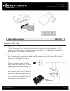
Wiring Descriptions CM6200
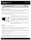
Connector 1 (CN1), 6-Pin
Pin 1 White – Accessory 12V positive (+) output. This wire must be connected to the vehicle accessory
/ HVAC blower motor wire. The proper wire will test 0V with the key in the off position, (+) 12V
while key is in the on position, 0V while cranking and back to (+) 12V when the key is returned to
the on position. This wire has a 20 amp fuse on it.
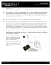
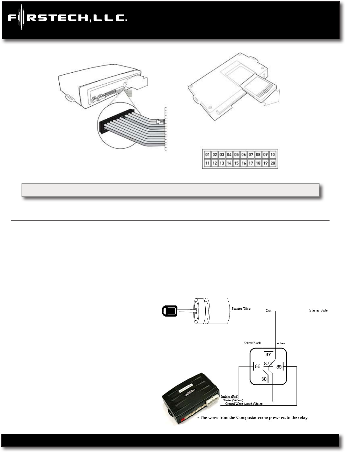
Pin 2 Yellow - Starter 12V positive (+) output. This wire is pre-wired to Pin 87a of the anti-grind/starter-kill
relay. This wire must be connected for remote start. The proper wire will test 0V with the key in the off
position, 0V while the key is in the on
position and (+) 12V during crank.
There are two wires coming off of the
relay; yellow-black and yellow. To utilize
the anti-grind or starter-kill features, the
vehicles starter wire must be cut in half,
otherwise, cut the relay out of the harness
and connect the yellow (Pin 6) directly to
the vehicles’ starter wire. The starter kill/
anti grind relay has a thin 24 guage blue
wire. This must be connected to pin 1 (24
guage blue wire) on Connector 3.