


Copyright 2009 Firstech, LLC.
Page 16
CM6200 Install Guide
Starter System
www.firstechonline.com | www.compustar.com
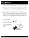
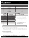
Pin 18 Gray/Black – Hood Pin negative (-) input. This input is a safety shut down and alarm trigger. It prevents
the vehicle from remote starting while the hood is open and triggers the alarm if the hood is opened
while the alarm is armed. You can connect this wire to the hood pin supplied with this kit, or to a wire in
the vehicle that shows (-) only while the hood is open.
Pin 19 Violet [POC 9] - Violet [POC 9] - Auxiliary 1 - 250mA negative (-) output. This is an optional output
that will provide a pulsed, latched, or timed negative output when triggered by the remote(s). This can
be used for power sliding doors, window modules or other outputs.
Pin 20 Brown - Siren 12V positive (+) output. Connect this wire to the (+) wire located on the siren. To change
siren output settings, review Option 3-7.
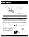
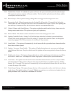
Connector 4 (CN3) , 20 Pin Blade Connector - New Generation
This connector is used only if you are installing a Blade-AL or Blade-TB. The wiring harness for this connector
only comes with the Blade cartridge. Please refer to the Blade install guide for wire descriptions. The new CM6
Series the Blade connector has a locking tab. Non-locking tab blade harnesses will work but you MUST
TAKE CARE TO NOT PLUG THE HARNESS IN UPSIDE DOWN. Make sure the two notches on the top
of the harness face the top (CM and barcode sticker side) of the brain. When looking at the wire side of the har-
ness the two notches must be at the top of the plug.
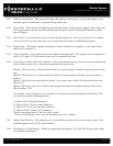
Connector 5 (CN4), 6-Pin
Pin 1 Not used
Pin 2 Violet/White - Trunk release 250mA negative (-) output. This is an optional output that will release the
trunk. Use CN1, Pin 2 if the vehicle is equipped with a (+) trunk release. System will unlock doors and
disarm alarm prior to trunk release.
Pin 3 Orange/Black - 2nd Unlock 250mA negative (-) output. This is an optional output that will provide a (-)
pulse for driver’s priority door lock. IMPORTANT: You must isolate the driver’s door and turn on Op
tion 1-3.
Pin 4 Blue - Unlock 250mA negative (-) output. This is an optional output that will provide a (-) pulse for
unlocking doors. System will unlock doors and disarm alarm. IMPORTANT: You must reverse polarity
for (+) trigger door lock systems. For additional lock settings review Option Group 1 (page 31).
Pin 5 Blue/Black - Lock 250mA (-) negative output. This is an optional output that will provide a (-) pulse for
locking doors. System will lock doors and arm alarm. IMPORTANT: You must reverse polarity for (+)
trigger door lock systems. For additional lock settings review Option Group 1 (page 31).
Pin 6 Not used