CM6200 Install Guide
Starter System
www.firstechonline.com | www.compustar.com
Copyright 2009 Firstech, LLC.
Page 15
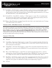
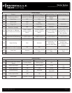
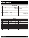
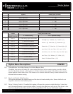
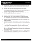
Pin 11 Black [POC 5] – Status/Ground while running 250mA negative (-) output. This is an optional output that
will provide a negative (-) output before the ignition cranks and stay on throughout the remote start dura
tion. This wire is most commonly used to trigger bypass / transponder modules.
Pin 12 Brown/White - This is a dual-purpose wire that is selectable through Option 4-9 in the programming
able. Select the polarity through the glow/key jumper on the control module. It can be set to ac
cept either a positive (+) or negative (-) wait to start input / key sense.
Default – Glow plug positive (+) or negative (-) input. The proper vehicle wire will show a (+) or (-)
trigger while the wait to start light is on. This wire will delay the starter output momentarily to allow the
glow plugs to warm up on vehicles equipped with a diesel engine. You can adjust the delay with Option
2-3.
Optional – Key sense positive (+) or negative (-) input. The proper wire will show a (+) or (-) trigger
only when the key is in the ignition. The purpose of the key sense is to prevent the system from passively
arming or setting reservation mode while the key is still in the ignition.
Pin 13 Orange [POC 6] - Factory Arm 250mA negative (-) output. This is an optional output that will provide a
(-) pulse during lock, after crank and again after the ignition shuts down.
Pin 14 Pink - Slave/Closed Loop negative (-) input. This is a dual-purpose optional input that can be changed
through Option 4-10.
Default: Slave/Timer Start (-) input. This is most commonly used when adding a remote start to a fac
tory keyless entry system. You can adjust the number of pulses with Option 2-4.
Optional: Closed Loop (-) input. This wire acts as an instant trigger when separated from ground (-). It
is most commonly used to protect headlights or trailers.
Pin 15 Orange/White [POC 7] - Factory Disarm 250mA negative (-) output. This is an optional output that will
provide a (-) pulse during unlock and prior to the ignition turning on.
Pin 16 Yellow/Black - Engine sensing input. This wire is connected to the vehicles Tach or Alternator wire and
is required if you are not using the no tach sense setting. IMPORTANT: To change engine-sen
ing modes, you must change Option 2-10; Default requires a Tach input.
Pin 17 White [POC 8] - Horn honk 250mA negative (-) output. This is an optional output that will pulse the
factory horn. The proper wire will show ground (-) while the horn is sounding. To change horn
output settings, review Options 3-8 and 3-9.


