


CM6200 Install Guide
Starter System
www.firstechonline.com | www.compustar.com
Copyright 2009 Firstech, LLC.
Page 14
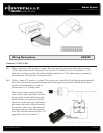
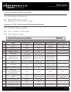
Connector 3 (CN2), 20-Pin: Programmable Output Connector (POC)
IMPORTANT: Odd Pin numbers 1 through 17 are programmable for up to 12 different output types. Refer to
Special Option Group 2 for details.
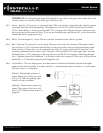
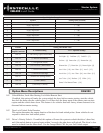
Pin 1 Blue - 250mA negative (-) output when armed and during remote start (while running). This wire is
pre-wired to the anti-grind/starter-kill relay. Caution: When this wire is being used to trigger aftermarket
accessories it must be diode isolated.
Pin 2 Orange/Black - Parking Light Reminder (-) input that monitors the vehicle’s parking lights. It prevents
the unit from setting Reservation Mode if this wire sees input.
Pin 3 Green/White [POC 1] - Parking light 250mA negative (-) output. The proper wire will test (-) when the
parking light switch is in the on position.
Pin 4 Light Blue – Parking / Emergency brake negative (-) input. This input is required for manual transmis
sion/reservation and turbo-timer mode. The proper wire will provide a (-) trigger when parking / emer
gency brake is set.
Pin 5 Red/Black [POC 2] – 2nd Starter 250mA negative (-) output. This output can be used to trigger the pre-
wired relay located on the main ignition harness.
Pin 6 Light Blue/White - Brake 12V positive (+) input. This input must be connected as it provides a shut
down for the remote start. The proper wire will test (+) 12V while the foot brake is pressed.
Pin 7 Green [POC 3] - 2nd Ignition 250mA negative (-) output. This output can be used to trigger the pre-
wired relay located on the main ignition harness.
Pin 8 Violet/Black - Trunk negative (-) input. This is an optional input that will monitor when the vehicle’s
trunk has been opened. The proper wire will provide a (-) trigger while the trunk is open.
Pin 9 White/Black [POC 4] - 2nd Accessory 250mA negative (-) output. This output can be used to trigger the
pre-wired relay located on the main ignition harness.
Pin 10 Red/White - Door trigger input. This wire monitors negative (-) or positive (+) trigger door-pins. The
proper wire will provide a (-) trigger or a (+) trigger only when the doors are opened. You will need to
test the wire for proper polarity and set door dip switch on the control module for the corresponding
polarity. IMPORTANT: This wire is required for manual transmission remote starts.