


their originally fitted sequence and note in
which direction the seal lips are located.
11 Inspect the surfaces of the piston and
cylinder bore. If scoring, corrosion or
metal-to-metal rubbing areas are evident,
renew the master cylinder complete.
12 If the components are in good condition,
discard the oil seals and manipulate the new
ones into position, using the fingers only.
13 Refit by reversing the removal operations;
apply pressure to the piston ends so that the
stop bolts can be fitted, then tighten the end
plug. Make sure that the grooves in the
pistons engage in the stop bolts.
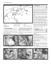
14 Before refitting the master cylinder to the
servo, measure the projection of the servo
piston pushrod. When the master cylinder is
fitted, there must be a clearance (see A in
Fig. 8.7) between the end of the pushrod and
the primary piston end face of between 0.825
and 1.025 mm (0.03 and 0.04 in). A depth
gauge will be required for these
measurements, the reference point being the
mating surfaces of the master cylinder and the
vacuum servo.
15 Alter the adjusting screw on the servo as
necessary and lock it by applying locking fluid
to the threads on completion.
16 Bolt the master cylinder to the vacuum
servo or bulkhead, then reconnect the
pipelines and reservoir cap leads.
17 Bleed the complete hydraulic system, as
described in Section 12.
10 Pressure regulating valve
3
1 The pressure regulating valve is a load
proportioning valve which restricts the
hydraulic pressure to the rear brakes
according to car weight during heavy
applications of the brake pedal. This prevents
the rear wheels locking.
2 A faulty or non-operational valve should be
renewed complete, no repair being possible.
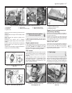
3 To remove the valve, unscrew the pipe
unions and disconnect the hydraulic pipes
from the valve. Cap the ends of the pipes to
prevent loss of fluid.
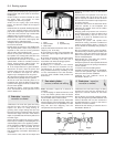
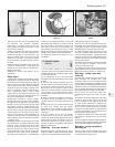
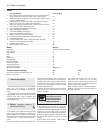
4 Unbolt the valve mounting bracket,
withdraw it and disconnect the tension spring
(photo).
5 Refit the new valve and then adjust it in the
following way.
6 Have the car standing on a level floor.
7 The car should be normally loaded (kerb
weight) with fuel, oil, spare wheel etc. Load
the luggage compartment immediately behind
the seat back with:
65 kg (143 lbs) on three-door models or
55 kg (121 lbs) on five-door models
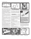
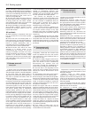
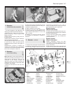
8 Refer to Fig. 8.10 and slacken the valve
bracket securing bolt (1).
9 Attach a 6.0 kg (13.2 lb) weight to the
bracket eye (2) as shown and then tighten the
bracket securing bolt.
10 Bleed the braking system if a new valve
has been fitted. Bleeding will not of course be
required if only adjustment has been carried
out to an existing valve.
11 Hydraulic hoses and pipes -
inspection and renewal
3
Flexible hoses
1 Periodically, all brake pipes, pipe
connections and unions should be completely
and carefully examined.
2 First examine for signs of leakage where the
pipe unions occur. Then examine the flexible
hoses for signs of chafing and fraying and, of
course, leakage. This is only a preliminary part
of the flexible hose inspection, as exterior
condition does not necessarily indicate the
interior condition, which will be considered
later.
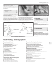
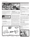
3 Flexible hoses are always mounted at both
ends in a rigid bracket attached to the body or
a sub-assembly. To remove them, it is
necessary first of all to unscrew the pipe
unions of the rigid pipes which go into them.
8•6 Braking system
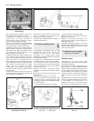
Fig. 8.11 Typical hydraulic hose connection
(Sec 11)
Fig. 8.10 Weight attachment point for
pressure regulating valve adjustment (Sec 10)
1 Fixing bolt 2 Bracket eye
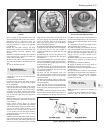
Fig. 8.9 Components of the pressure
regulating valve (Sec 10)
Fig. 8.8 Pressure regulating valve (Sec 10)10.4 Pressure regulating valve bracket and
tension spring